Sterilization device for medical equipment

A technology of sterilization device and medical equipment, applied in water supply devices, cleaning methods and utensils, chemical instruments and methods, etc., can solve the problems of unclean cleaning, cleaning dead corners, time-consuming and laborious, etc. Easy-to-use effects

Inactive Publication Date: 2018-07-13
王华
View PDF0 Cites 5 Cited by
  • Summary
  • Abstract
  • Description
  • Claims
  • Application Information

AI Technical Summary

Problems solved by technology

[0002] Nowadays, in medical institutions, it is necessary to clean and disinfect different types of medical instruments. It is difficult to clean medical instruments. Manual cleaning is not only time-consuming and laborious, but also prone to cleaning dead ends, cleaning is not clean, and the cleaned medical instruments need to be cleaned. Further disinfection treatment is slow and inefficient, and is not suitable for batch medical device cleaning and disinfection treatment
When using a cleaning machine for cleaning and disinfection, the medical equipment is generally placed directly in the disinfection box, and the disinfectant is poured into the washing machine, which makes it difficult to clean the adherents on the surface of the medical equipment, resulting in poor cleaning effect, and the disinfectant is in the process of cleaning The machine is relatively static and does not flow, which reduces the cleaning effect of medical devices, and the cleaned dirt is difficult to separate from the disinfectant, and is discharged together with the disinfection. The disinfectant cannot be used multiple times, which increases the cost of cleaning and disinfection of medical devices.

Method used


Image

  • Sterilization device for medical equipment
  • Sterilization device for medical equipment
  • Sterilization device for medical equipment

Examples


Embodiment Construction

[0020] The following will clearly and completely describe the technical solutions in the embodiments of the present invention with reference to the accompanying drawings in the embodiments of the present invention. Obviously, the described embodiments are only some, not all, embodiments of the present invention.

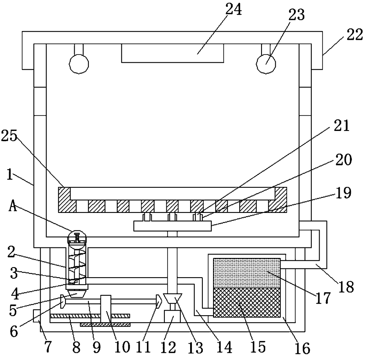
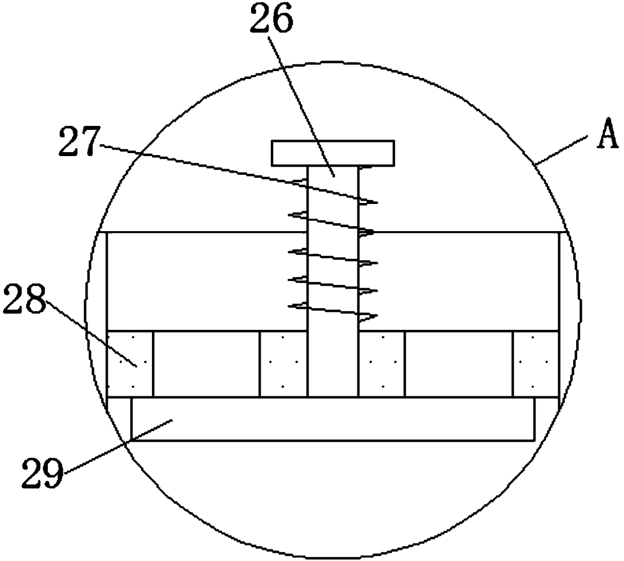
[0021] refer to Figure 1-3 , a sterilizing device for medical equipment, comprising a cylinder body 1, a casing 2 is fixedly installed on the outer wall of the bottom end of the cylinder body 1, the casing 2 communicates with the cylinder body 1, and guide plates 28 are welded on the inner walls of both sides of the casing 2, The guide plate 28 is movably worn with a guide rod 26, the guide rod 26 is covered with a spring 27, one end of the guide rod 26 is welded with a baffle plate 29, the guide rod 26 is a T-shaped structure, and the spring 27 is positioned at the level of the guide plate 28 and the guide rod 26 Between the parts, the baffle plate 29 is located at...


PUM


Abstract

The invention discloses a sterilization device for medical equipment. The device comprises a cylinder body; a shell is fixedly installed on the outer wall of the bottom end of the cylinder body; the shell is communicated with the cylinder body; two guide plates are respectively welded on the inner walls of the two sides of the shell; a guide rod movably passes through each guide plate, a spring sleeves each guide rod, a baffle plate is welded at one ends of the guide rods, the guide rods separately are of a T-shaped structure, the springs are positioned between the horizontal parts of the guide plates and the horizontal parts of the guide rods, and the baffle plate is positioned at the bottoms of the guide plates; each guide plate is provided with a plurality of water flow holes, and the water flow holes are blocked by the baffle plate; a first rotating rod is rotatably installed at the bottom end of the shell, and a helical blade is fixedly installed on a rod body of the first rotating rod and is positioned under the baffle plate; one end of the first rotating rod extends out of the shell and is fixedly provided with a first conical tooth; the bottom end of the cylinder body is rotatably provided with a connecting rod. The sterilization device for the medical equipment is reasonable in design and structure, simple to operate and convenient to use, can be conveniently used forcleaning and sterilizing, and also can recycle disinfectant fluid so as to lower the cost.

Description

technical field [0001] The invention relates to the technical field of sterilization of medical instruments, in particular to a sterilization device for medical instruments. Background technique [0002] Nowadays, in medical institutions, it is necessary to clean and disinfect different types of medical instruments. It is difficult to clean medical instruments. Manual cleaning is not only time-consuming and laborious, but also prone to cleaning dead ends, cleaning is not clean, and the cleaned medical instruments need to be cleaned. Further disinfection treatment is slow and inefficient, and is not suitable for batch cleaning and disinfection treatment of medical devices. When using a cleaning machine for cleaning and disinfection, the medical equipment is generally placed directly in the disinfection box, and the disinfectant is poured into the washing machine, which makes it difficult to clean the adherents on the surface of the medical equipment, resulting in poor cleanin...

Claims


Application Information

Patent Timeline
Patent Type & Authority Applications(China)
IPC IPC(8): A61L2/18A61L2/10A61L2/06A61L2/26B08B3/04B08B3/14
CPCA61L2/18A61L2/06A61L2/10A61L2/26A61L2202/17A61L2202/24B08B3/044B08B3/14
Inventor 王华
Owner 王华
Why Eureka
Try Eureka