Parts Grinding Device

A technology for parts and grinding discs, applied in the field of grinding equipment, can solve the problem of repeatedly clamping the grinding area, etc., to achieve the effect of wide grinding range, improving grinding efficiency, saving labor and labor costs

Active Publication Date: 2019-06-14
CHONGQING JIANAN IND & TRADE
View PDF12 Cites 0 Cited by
  • Summary
  • Abstract
  • Description
  • Claims
  • Application Information

AI Technical Summary

Problems solved by technology

[0006] The object of the present invention is to provide a part grinding device to solve the problem that the parts need to be clamped repeatedly and the grinding area is small

Method used


Image

  • Parts Grinding Device
  • Parts Grinding Device
  • Parts Grinding Device

Examples


Embodiment Construction

[0021] The present invention will be described in further detail below by means of specific embodiments:

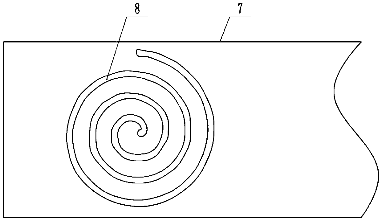
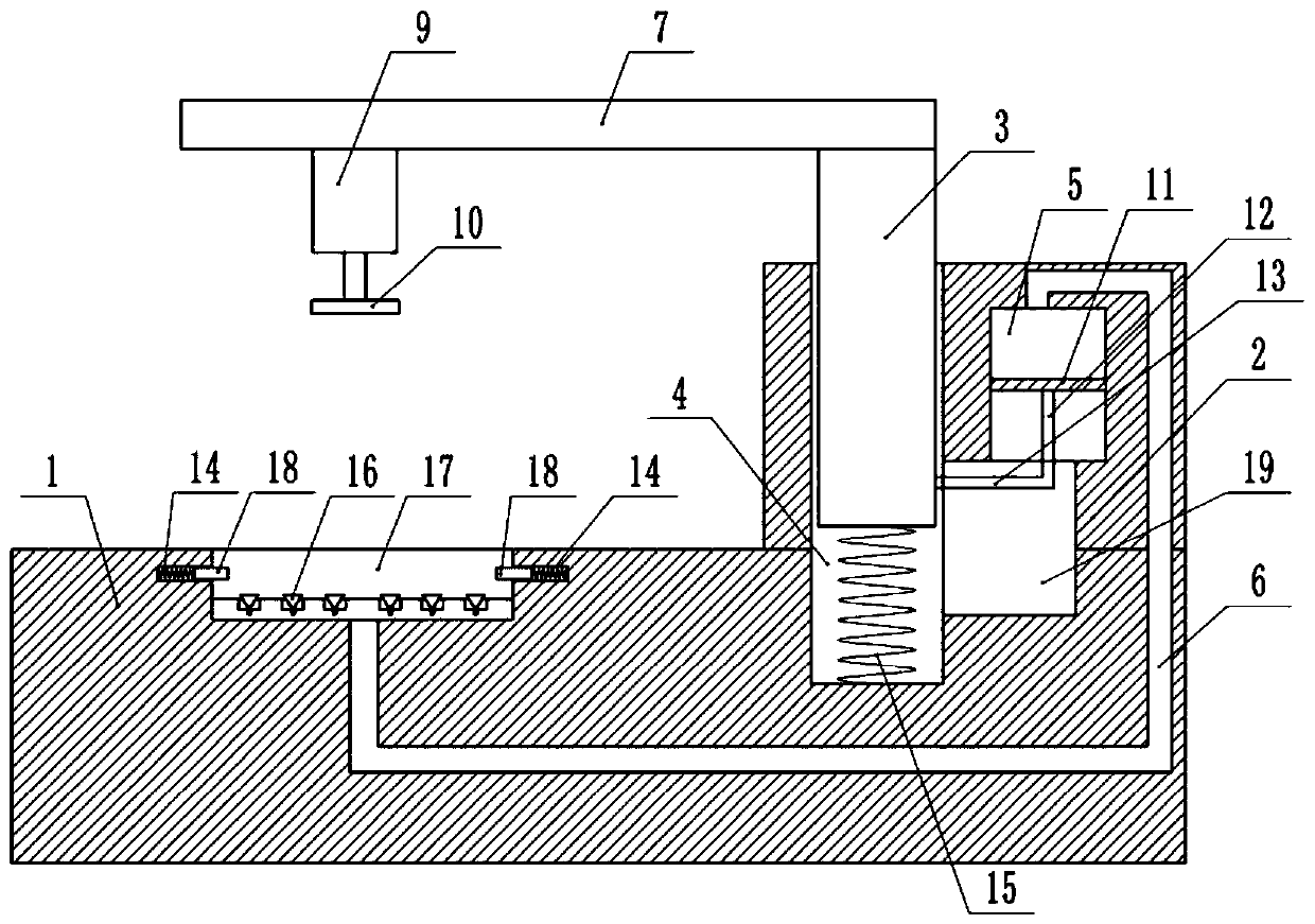
[0022] The reference signs in the drawings of the description include: base 1, upright column 2, support column 3, first cavity structure 4, second cavity structure 5, third cavity structure 6, horizontal plate 7, spiral guide rail 8, motor 9. Grinding disk 10, piston 11, piston rod 12, cross bar 13, first spring 14, second spring 15, sucker 16, groove 17, slider 18, chute 19.

[0023] Such as figure 1 As shown, the part grinding device includes a base 1 and an air pump. The air pump has the functions of pumping air and inflating air. The right end of the base 1 is equipped with a column 2, and the column 2 is provided with a columnar first cavity structure 4 and a second cavity structure 5. , the upper end of the first cavity structure 4 is provided with a first opening, the lower end of the second cavity structure 5 is provided with a second opening, and the bottom of ...


PUM


Abstract

The invention relates to the technical field of polishing devices and specifically discloses a part polishing device. The part polishing device comprises a base and an air pump, wherein an upright column is arranged on the base; a first cavity structure, a second cavity structure and a third cavity structure are arranged on the upright column; a support column is arranged in the first cavity structure; a transverse plate is arranged at an upper end of the support column; a spiral track is arranged on the transverse plate; a sliding frame is arranged in the spiral track; a motor is arranged onthe sliding frame; a polishing disc is arranged at a shaft end of an output shaft of the motor; a piston is arranged in the second cavity structure; a piston rod is arranged on the piston; a transverse rod is connected between the piston rod and the support column; a plurality of adsorption holes is formed in the base; a suction disc is arranged in the adsorption hole; an air suction inlet is formed in the suction disc; and the third cavity structure is in communication with the air suction inlet and the second cavity structure. The part polishing device provided by the invention is mainly used for polishing parts and solves the problem of small polishing area during part polishing.

Description

technical field [0001] The invention belongs to the technical field of grinding equipment, and specifically discloses a part grinding device. Background technique [0002] In the modern manufacturing industry, the maintenance efficiency of the equipment is increased through batch processing of the parts on the equipment, and at the same time, it provides a guarantee for the normal operation of the equipment. When the equipment fails, the equipment can be quickly restored by quickly replacing the parts and accessories. The running state of the machine improves the manufacturing efficiency. [0003] Parts are usually made by casting, stamping, etc. The parts processed by casting, stamping, etc. usually have burrs, and the parts need to be polished before forming. The existing grinding equipment grinds the parts unevenly, which makes the grinding effect not good. Ideal, thus affecting the use of the next process. [0004] In view of the above problems, Chinese patent CN107498...

Claims


Application Information

Patent Timeline
Patent Type & Authority Patents(China)
IPC IPC(8): B24B9/02B24B41/06B24B41/02
CPCB24B9/02B24B41/02B24B41/06
Inventor 肖福禄
Owner CHONGQING JIANAN IND & TRADE
Why Eureka
Try Eureka