Remote sensing emergency monitoring and command vehicle

A command vehicle and remote sensing technology, applied to motor vehicles, goods transport vehicles, vehicles used for freight, etc., can solve problems that affect emergency decision-making, poor compatibility between application software and acquisition equipment, and incomplete configuration functions, so as to meet the needs of mobility and real-time performance, avoid laborious lifting and transportation, and have no effect of generator paint smell

Inactive Publication Date: 2018-07-13
TIANJIN ZHONGKE REMOTE SENSING INFORMATION TECH
View PDF1 Cites 6 Cited by
  • Summary
  • Abstract
  • Description
  • Claims
  • Application Information

AI Technical Summary

Problems solved by technology

However, in many places, the emergency monitoring capabilities cannot keep up with the occurrence of sudden disasters. Many emergency monitoring agencies lack on-site remote sensing data acquisition equipment. Even if there are corresponding instruments and equipment, the monitoring capabilities are insufficient due to incomplete configuration functions. It cannot reflect the actual situation and seriously affects the emergency decision-making of relevant departments
[0004] With the advancement of remote sensing technology, all units have now improved their remote sensing emergency response capabilities, but the area of ​​the collected data is too limited to a certain point and is not representative. The data processing ability is not real-time enough to allow monitoring personnel to discover dangers in the first time and take emergency measures in time, which delays the timing of emergency relief
In addition, the remote sensing data acquisition equipment is too large, which limits the function of the equipment, and the poor compatibility of various application software and acquisition equipment is also the deficiency of the existing equipment.

Method used


Image

  • Remote sensing emergency monitoring and command vehicle
  • Remote sensing emergency monitoring and command vehicle
  • Remote sensing emergency monitoring and command vehicle

Examples


Embodiment Construction

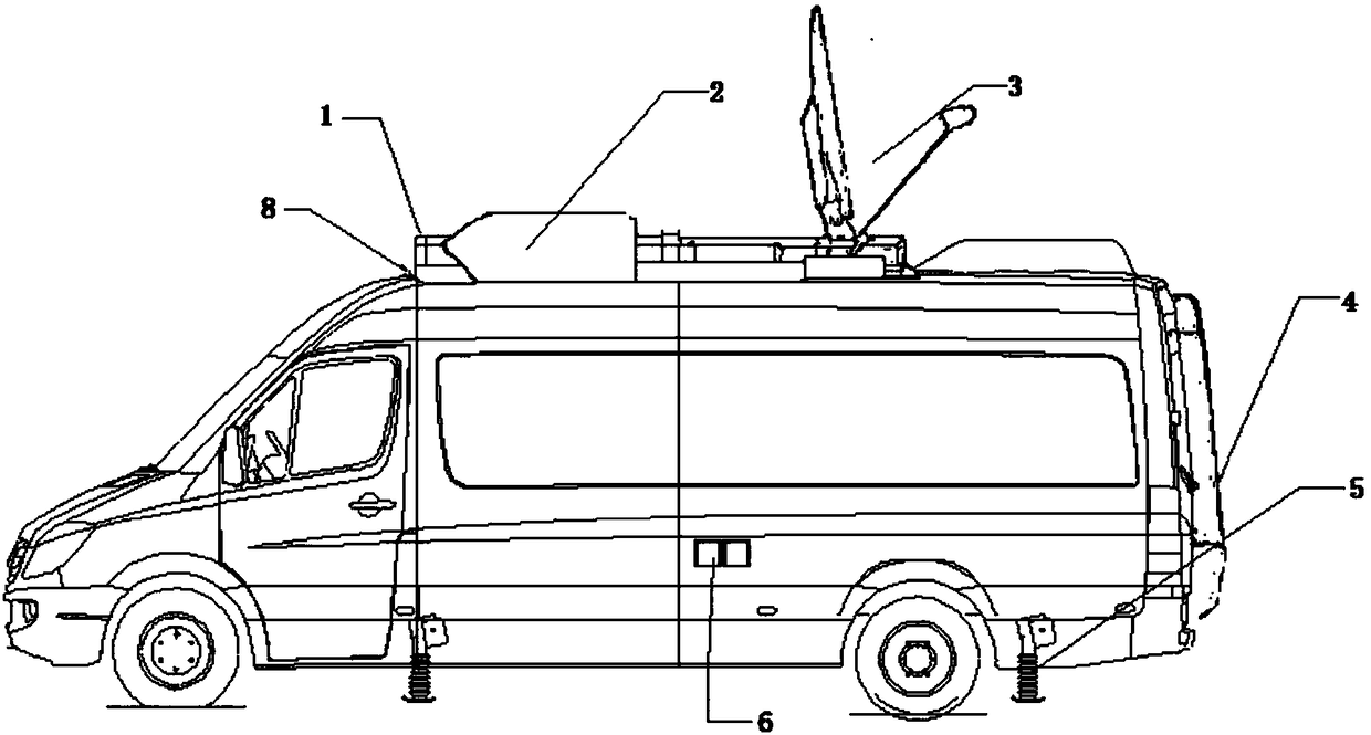
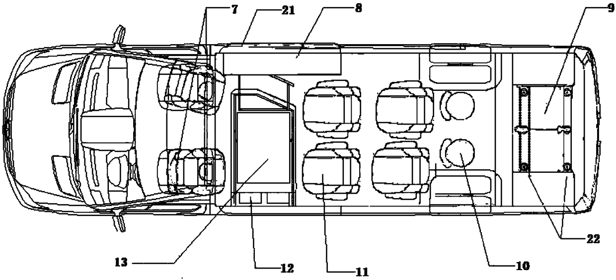
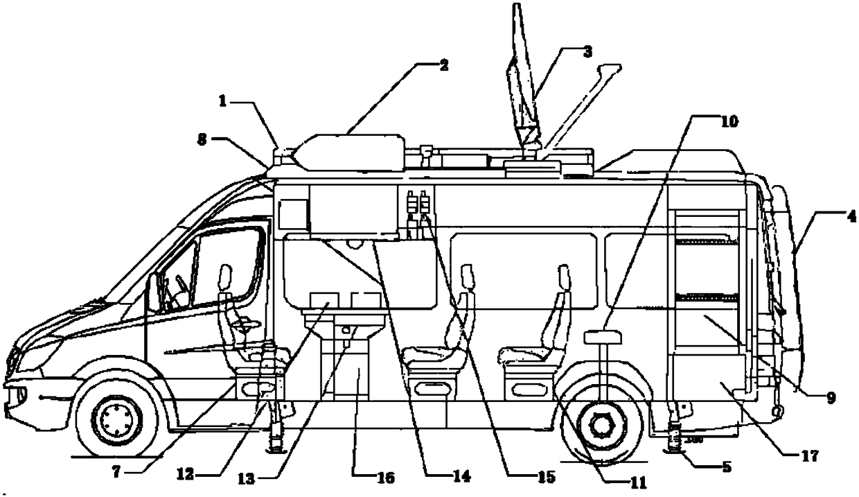
[0034] The present invention will be described in further detail below through specific embodiments and in conjunction with the accompanying drawings.

[0035] As shown in Figures 1-4, a remote sensing emergency monitoring and command vehicle described in the embodiment of the present invention is equipped with a roof platform 1, wherein a parking air conditioner 2, a satellite antenna 3 and an awning 8 are fixed on the roof platform 1 above; the satellite antenna 3 can ensure access to the Internet, and can perform various information inquiries, file transfers and data exchange; the parking air conditioner 2 is to adjust the ambient temperature in the compartment to ensure the normal operation of the instrument; the awning 8 is fixed on the vehicle. The outside of the right side of the top platform is used to build a simple work area in the field. The climbing ladder 4 is located on the rear door of the compartment, allowing crew to access the roof when required. The chassis...


PUM


Abstract

The invention discloses a remote sensing emergency monitoring and command vehicle. The vehicle includes a roof platform, a parking air conditioner, a satellite antenna, a climbing ladder, a chassis support, an external power supply, a front and rear driving seat, an awning, an engineering group cabinet, a round stool, a single people seat, a tablet computer, a touch display screen workbench, a liquid crystal display screen group, a vehicle-mounted inter-phone, a locker, an equipment bracket, a surveillance camera, an engineering group computer operating platform, a shock absorbing pad, an emergency communication device, a remote sensing data acquisition device, a data processing and output device, a high-resolution satellite data push device, a command and dispatch and press release device and an expert remote conference device. The vehicle has the advantages that monitoring equipment required for remote sensing emergency monitoring and command is integrated in a vehicle compartment,and the vehicle can comprehensively collect and process remote sensing information at fixed site and timing, and provide intuitive data products and emergency solutions to meet the liquidity and real-time properties of emergency disaster relief.

Description

technical field [0001] The invention relates to the technical field of aviation remote sensing emergency monitoring, in particular to a remote sensing emergency monitoring and command vehicle. Background technique [0002] Aviation remote sensing emergency monitoring means that after a disaster occurs, the disaster relief command and decision-making body needs to obtain on-site information as soon as possible to conduct disaster assessment. Therefore, obtaining remote sensing data that meets the needs of disaster assessment has become an urgent goal, and timeliness is the focus of ensuring aviation remote sensing emergency monitoring tasks Solve the problem. [0003] After a sudden disaster event occurs, use remote sensing emergency monitoring and command vehicles to obtain remote sensing data in the sudden disaster area. scope and extent. Remote sensing emergency monitoring includes the monitoring of major engineering accidents, sudden pollution accidents, and natural dis...

Claims


Application Information

Patent Timeline
Patent Type & Authority Applications(China)
IPC IPC(8): B60P3/00
CPCB60P3/00
Inventor 王晋年丁琳黄瑶李丹李增顺郝震寰张彩霞刘净净
Owner TIANJIN ZHONGKE REMOTE SENSING INFORMATION TECH
Why Eureka
Try Eureka