
Hole system position determining method for cylinder body of engine

A technology of engine block and determination method, applied in the field of information, can solve the problems of cumbersome and complicated limit size and low accuracy, and achieve the effect of improving design efficiency and accuracy

Inactive Publication Date: 2018-07-13
XIAMEN UNIV OF TECH
View PDF4 Cites 5 Cited by
  • Summary
  • Abstract
  • Description
  • Claims
  • Application Information

AI Technical Summary

Problems solved by technology

[0003] In view of this, the purpose of the embodiment of the present invention is to provide a method for determining the position of the hole system of the engine cylinder, so as to improve the limit size used in the study of the position of the hole system of the engine, such as the extremum method, which is cumbersome and has low accuracy. The problem

Method used


Image

  • Hole system position determining method for cylinder body of engine
  • Hole system position determining method for cylinder body of engine
  • Hole system position determining method for cylinder body of engine

Examples


Embodiment Construction

[0026] The following will clearly and completely describe the technical solutions in the embodiments of the present invention with reference to the accompanying drawings in the embodiments of the present invention. Obviously, the described embodiments are only some, not all, embodiments of the present invention. The components of the embodiments of the invention generally described and illustrated in the figures herein may be arranged and designed in a variety of different configurations. Accordingly, the following detailed description of the embodiments of the invention provided in the accompanying drawings is not intended to limit the scope of the claimed invention, but merely represents selected embodiments of the invention. Based on the embodiments of the present invention, all other embodiments obtained by those skilled in the art without making creative efforts belong to the protection scope of the present invention.

[0027] The method for determining the position of th...


PUM


Abstract

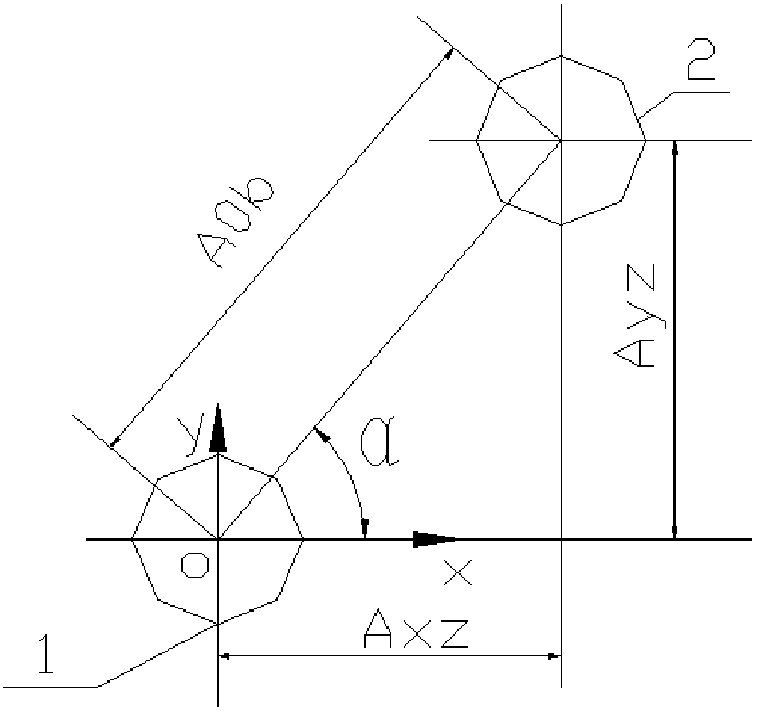
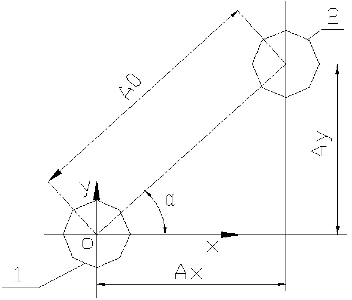
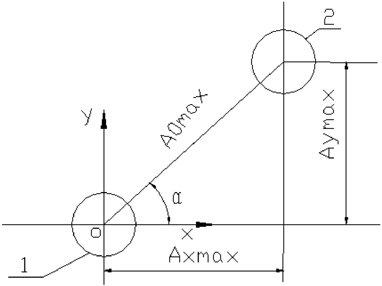
The embodiment of the invention provides a hole system position determining method for a cylinder body of an engine. The method comprises the steps of simulating hole system machining and a hole system position determining process, determining a relationship between hole system position coordinates and a hole center distance dimension, establishing a dimension-chain two-dimensional model of the relationship between the hole system position coordinates and the hole center distance dimension, and determining a closed ring; designing the dimension of the closed ring and the position of a reference hole, and establishing a two-dimensional model of the hole system machining position coordinates; obtaining the dimensions of the hole system machining position coordinates according to the two-dimensional model of the hole system machining position coordinates. According to the method, by establishing the two-dimensional model of the hole system machining position coordinates, the basic dimension, maximum limit dimension and minimum limit dimension of the machining position coordinates of a hole system can be visually and accurately presented. By establishing the dimension-chain two-dimensional model, determining the closed ring, based on the design of the closed ring and the reference hole, the two-dimensional model of the hole system machining position coordinates is established, andthe efficiency and accuracy of designing the dimensions of the hole system machining position coordinates can be improved.

Description

technical field [0001] The invention relates to the field of information technology, in particular to a method for determining the position of an engine cylinder hole system. Background technique [0002] In the drawings currently used in production, the positional relationship of some associated elements of parts to the datum is controlled by the positioning limit size. Correct analysis of the tolerance zone determined by these positioning limit dimensions is directly related to whether the processing technology and inspection method can meet the requirements. To study the limit size, the extreme value method is often used, that is, to calculate through the size chain and calculation formula. However, this kind of calculation method is not intuitive, and there are some calculation parameter errors. Contents of the invention [0003] In view of this, the purpose of the embodiment of the present invention is to provide a method for determining the position of the hole syst...

Claims


Application Information

Patent Timeline
IPC IPC(8): G06F17/50G06T11/20
CPCG06T11/206G06F30/17
Inventor 刘金武易子超陈阿龙梅丽芳
Owner XIAMEN UNIV OF TECH
Learn More