
Reinforcement cage molding assembler

A technology for assembling machines and steel cages, which can be applied to online nets, other household appliances, household appliances, etc., can solve the problems of high labor intensity, low production efficiency, and failure to cover steel cages, etc., to achieve fast and convenient adjustment, simple and convenient positioning, and improved The effect of production efficiency

Pending Publication Date: 2018-07-17
TJK MACHINERY TIANJIN
View PDF0 Cites 25 Cited by
  • Summary
  • Abstract
  • Description
  • Claims
  • Application Information

AI Technical Summary

Problems solved by technology

There are two types of reinforcing cage molding in the prior art, one is for reinforcing cages with standard circular cross-sections, and the manufacturing process is that the welding cage machine equipment positions the main reinforcement through the round holes set on the fixed plate and the moving plate, and then The fixed plate and the moving plate rotate synchronously in the same direction, and the stirrups are pulled out from the coil material plate and wound on the main bars with the help of their rotating power. At this time, the welding head welds the intersection point, and its disadvantage is that it cannot cover all cross-sections. Reinforcement cages, such as squares, rectangles, triangles, polygons, etc.; the other is to make the stirrups of the reinforcement cage in advance with the help of bending hoop equipment, and then place the stirrups on the suspended main reinforcement according to the specifications of the reinforcement cage. Binding, and then binding the remaining main bars according to the specifications of the steel cage, and then welding as a whole after the binding is completed. The defects of this production method are low production efficiency and high labor intensity, which cannot meet the needs of mass production.

Method used


Image

  • Reinforcement cage molding assembler
  • Reinforcement cage molding assembler
  • Reinforcement cage molding assembler

Examples


Embodiment Construction

[0034] The technical solutions of the present invention will be further described below in conjunction with the accompanying drawings and embodiments. It should be understood that the specific embodiments described here are only used to explain the present invention, but not to limit the present invention. In addition, it should be noted that, for the convenience of description, only the parts related to the present invention are shown in the drawings but not all of them.

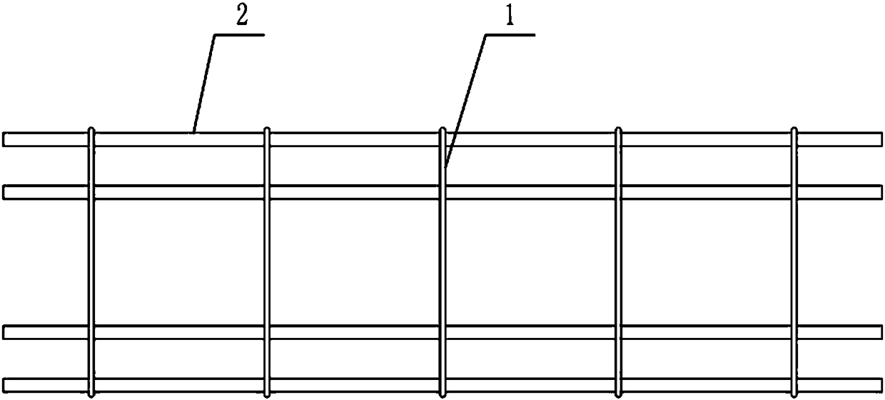
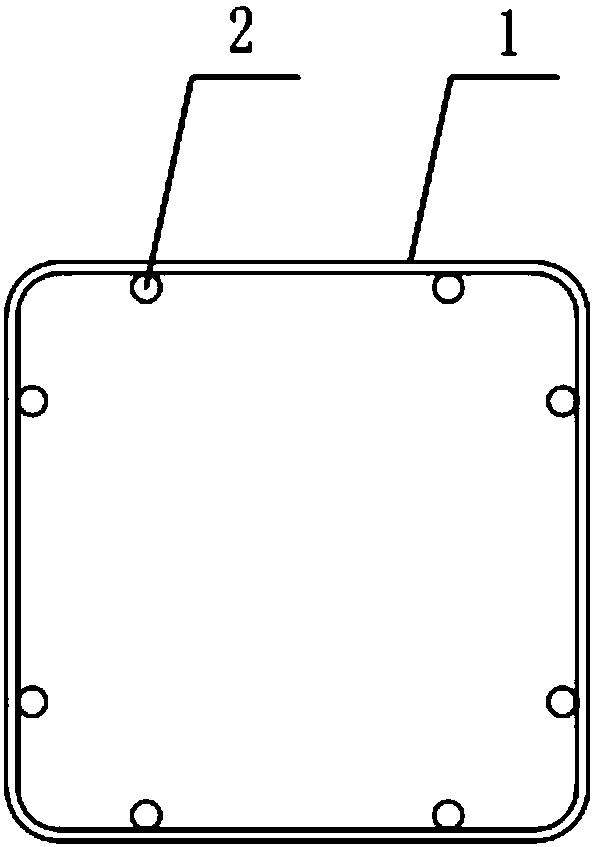
[0035] Such as figure 1 and figure 2 As shown, the reinforcement cage includes a stirrup 1 and a main reinforcement 2, a plurality of stirrups 1 are distributed at intervals, and a plurality of main reinforcements 2 are evenly spaced along the inner peripheral surface of the stirrup 1 and are welded and fixed with the stirrup 1. The cross section of the reinforcement cage can be be any shape, such as circle, polygon, etc.

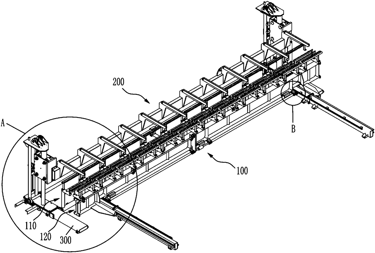
[0036] Such as Figure 3-Figure 8 As shown, the present invention provides a re...


PUM


Abstract

The invention relates to the technical field of reinforcement cage manufacturing, in particular to a reinforcement cage molding assembler. The reinforcement cage molding assembler comprises a stirruppositioning device and a main rib positioning device, wherein the stirrup positioning device comprises a fixed part and a movable part capable of moving relative to the fixed part; the movable part cooperates with the fixed part for fixing stirrups; and the main rib positioning device is arranged in a lifting manner relative to the stirrup positioning device, and is used for fixing main ribs and positioning the main ribs in different positions of the stirrups. Through self stirrup and main rib positioning modes, the reinforcement cage molding assembler not only can finish molding of reinforcement caged with various different section shapes, but also can simply and conveniently position the stirrups and the main ribs to save the work in such links as manual binding; and meanwhile, the stirrup positioning device and the main rib positioning device can be quickly and conveniently adjusted to adapt to manufacturing of the reinforcement cages with different specifications.

Description

technical field [0001] The invention relates to the technical field of steel cage production, in particular to a steel cage forming and assembling machine. Background technique [0002] Reinforcement cages are welded by stirrups and main reinforcements, mainly play a role in tensile strength, and are widely used in bridge construction, nuclear power, high-speed railways and other fields. There are two types of reinforcing cage molding in the prior art, one is for reinforcing cages with standard circular cross-sections, and the manufacturing process is that the welding cage machine equipment positions the main reinforcement through the round holes set on the fixed plate and the moving plate, and then The fixed plate and the moving plate rotate synchronously in the same direction, and the stirrups are pulled out from the coil material plate and wound on the main bars with the help of their rotating power. At this time, the welding head welds the intersection point, and its dis...

Claims


Application Information

Patent Timeline
IPC IPC(8): B21F27/20
CPCB21F27/20
Inventor 陈振东
Owner TJK MACHINERY TIANJIN
Learn More