A drilling device for construction based on multi-directional drilling technology

A drilling device and construction technology, applied in the direction of drilling/drilling equipment, boring/drilling, metal processing equipment, etc., can solve the problems of high risk, easy to be injured, time-consuming and labor-intensive tightening of bolts, etc. , to achieve flexible position control, improve drilling quality and ensure stability

Inactive Publication Date: 2020-01-21
NANTONG HAILITE RUBBER & PLASTIC MACHINERY
View PDF8 Cites 1 Cited by
  • Summary
  • Abstract
  • Description
  • Claims
  • Application Information

AI Technical Summary

Problems solved by technology

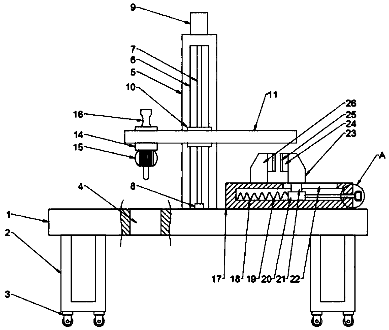
When the existing punching device is in use, in order to stably punch the object, the object is generally clamped by tightening the bolt. Although the hole can be stably punched, it is time-consuming and laborious to tighten the bolt, which makes it inconvenient to use, and the punching After the punching machine is finished, it is inconvenient to separate from the object, which once again causes the punching machine to be difficult to use; and the existing punching machine usually requires a hand-held punching machine to complete the work for the ground fixing device, but, This kind of hand-held punching machine is only suitable for drilling small holes. For some large holes, it cannot be completed, and the hand-held punching machine usually needs manual assistance to complete, which is relatively dangerous and prone to In the case of injury, it is very inconvenient to use

Method used


Image

  • A drilling device for construction based on multi-directional drilling technology
  • A drilling device for construction based on multi-directional drilling technology
  • A drilling device for construction based on multi-directional drilling technology

Examples


Embodiment Construction

[0022] It should be noted that, in the case of no conflict, the embodiments of the present invention and the features in the embodiments can be combined with each other.

[0023] In describing the present invention, it should be understood that the terms "center", "longitudinal", "transverse", "upper", "lower", "front", "rear", "left", "right", " The orientations or positional relationships indicated by "vertical", "horizontal", "top", "bottom", "inner" and "outer" are based on the orientations or positional relationships shown in the drawings, and are only for the convenience of describing the present invention and Simplified descriptions, rather than indicating or implying that the device or element referred to must have a particular orientation, be constructed and operate in a particular orientation, and thus should not be construed as limiting the invention. In addition, the terms "first", "second", etc. are used for descriptive purposes only, and should not be understood ...


PUM


Abstract

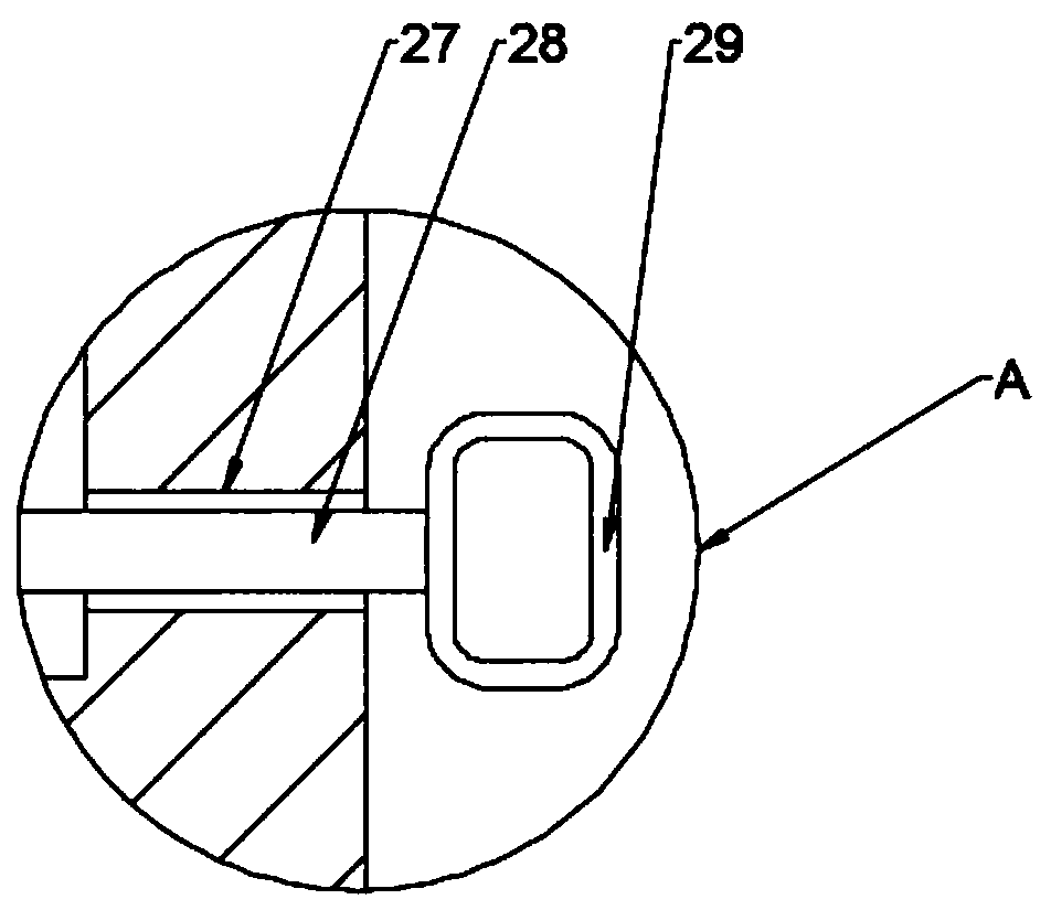
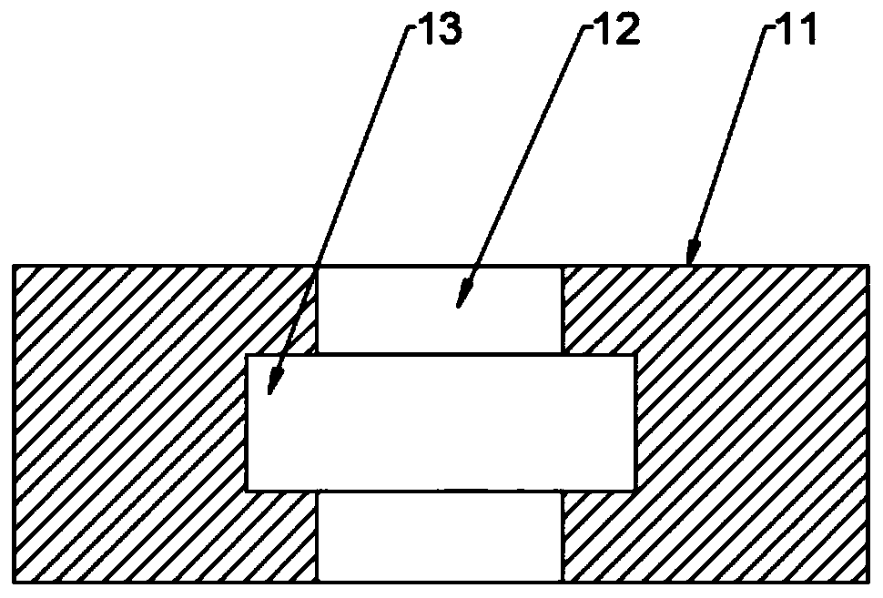
The invention discloses a building hole drilling device based on the multidirectional hole drilling technology. The building hole drilling device based on the multidirectional hole drilling technologycomprises a base plate. A guide hole is formed in the left side of the base plate. The right side of the top end face of the base plate is provided with a stand column and a clamping box seat. A motor is fixedly connected with the top end of the stand column. The front end face of the stand column is provided with a rail groove. A lead screw is arranged in the rail groove. The bottom end of the lead screw is rotationally connected to the bottom wall of the rail groove through a bearing seat. The top end of the lead screw penetrates through the top wall of the rail groove and is fixedly connected to a motor shaft of the motor. The lead screw is sleeved with a lifting seat matched with the rail groove. The front end face of the lifting seat is provided with a transverse plate. A transverseslot hole is formed in the transverse plate. The left side wall and the right side wall of the transverse slot hole are symmetrically provided with sliding grooves. A moving block matched with the sliding grooves is arranged in the transverse slot hole. The bottom end of the moving block is fixedly connected with a drilling machine. According to the building hole drilling device based on the multidirectional hole drilling technology, through the arrangement of the rail groove and the transverse plate, the drilling machine can move in multiple directions in space, position control is flexible,holes can be easily drilled in a ground fixed device and a movable object.

Description

technical field [0001] The invention relates to the technical field of building drilling equipment, in particular to a building drilling device based on multi-directional drilling technology. Background technique [0002] Construction engineering refers to the engineering entity formed through the construction of various housing buildings and their ancillary facilities and the installation activities of supporting lines, pipelines and equipment. Among them, "housing construction" refers to projects that have roofs, beams, walls, foundations, and can form internal spaces to meet people's needs for production, living, learning, and public activities. [0003] Construction engineering refers to the planning, survey, design and construction, completion and other technical work and the completed engineering entity and the installation project of the supporting lines, pipelines and equipment for new construction, reconstruction or expansion of houses, buildings and auxiliary struc...

Claims


Application Information

Patent Timeline
Patent Type & Authority Patents(China)
IPC IPC(8): B23B39/14
CPCB23B39/14
Inventor 朱园园
Owner NANTONG HAILITE RUBBER & PLASTIC MACHINERY
Why Eureka
Try Eureka