
Cloth cutting table for printing and dyeing

A cutting table, cloth technology, applied in the cutting of textile materials, textile and papermaking, metal processing and other directions, can solve problems such as poor practicability, and achieve the effect of strong practicability, preventing offset and improving cutting accuracy

Inactive Publication Date: 2018-07-17
侯如升
View PDF6 Cites 20 Cited by
  • Summary
  • Abstract
  • Description
  • Claims
  • Application Information

AI Technical Summary

Problems solved by technology

[0004] The purpose of the present invention is to provide a cloth cutting table for printing and dyeing, which has the advantage of strong practicability and solves the problem of poor practicability of the traditional printing and dyeing cloth cutting table

Method used


Image

  • Cloth cutting table for printing and dyeing
  • Cloth cutting table for printing and dyeing

Examples


Embodiment Construction

[0017] The following will clearly and completely describe the technical solutions in the embodiments of the present invention with reference to the accompanying drawings in the embodiments of the present invention. Obviously, the described embodiments are only some, not all, embodiments of the present invention. Based on the embodiments of the present invention, all other embodiments obtained by persons of ordinary skill in the art without making creative efforts belong to the protection scope of the present invention.

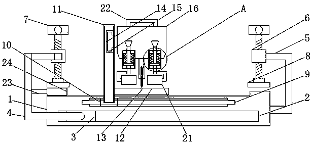
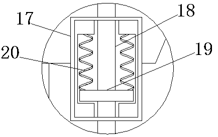
[0018] see Figure 1-2 , the present invention provides a technical solution: a cloth cutting table for printing and dyeing, including a base 1, the lower side of the front of the base 1 is provided with a first chute 2, and the inner cavity of the first chute 2 is movably connected with a first chute Block 3, the front of the first slider 3 is fixedly connected with the first curved plate 4, the right side of the middle part of the back of the first curved pl...


PUM


Abstract

The invention discloses a cloth cutting table for printing and dyeing. A first sliding chute is formed in the lower side of the front surface of a base, the inner cavity of the first sliding groove ismovably connected with a first sliding block, and threaded sleeves are fixedly connected to the rear side of a first curved plate and the right side of a second curved plate, the inner cavities of the threaded sleeves are in threaded connection with screw rods, and the bottoms of the two screw rods penetrate through the threaded sleeves to be movably connected with pressing plates; a second sliding chute is formed in the upper side of the front surface of the base, and the inner cavity of the second sliding chute is movably connected with a second sliding block; a holding plate is fixedly connected to the lower part of the right side of a supporting plate, and a third sliding chute is formed in the upper part of the right side of the supporting plate;and the inner cavity of cylindrical sleeves are connected with pull rods in a penetrating mode, and springs are fixedly connected to the two sides of the top of stop blocks, and pressing wheels are movably connected to the bottoms of theopposite sides of the two pull rods. According to the invention, the pressing wheels, the supporting plate, the springs, the third sliding groove, the screw rod, the pressing plates and the first sliding grooveare arranged, so that the cloth cutting table for the printing and the dyeing is enabled to be high in practicability.

Description

technical field [0001] The invention relates to the technical field of printing and dyeing equipment, in particular to a cloth cutting table for printing and dyeing. Background technique [0002] As we all know, in the equipment of the printing and dyeing factory, the cloth cutting table is a device for cutting the finished cloth to a certain size. [0003] The structure of the traditional cloth cutting table for printing and dyeing is relatively simple. During use, the cloth is fixed on the worktable and fixed by the clamping device. During the cutting process, the cutting knife will pull the cloth to a certain extent, which will As a result, the traditional cloth cutting table for printing and dyeing lacks a structure for real-time clamping of the cloth during the cutting process, and it is prone to cutting size errors, which leads to poor practicability of the traditional cloth cutting table. There was a problem. Contents of the invention [0004] The object of the pr...

Claims


Application Information

Patent Timeline
IPC IPC(8): B26D1/18B26D7/20B26D7/02B26D5/10D06H7/00
CPCB26D1/185B26D5/10B26D7/02B26D7/20D06H7/00
Inventor 侯如升
Owner 侯如升
Features
  • Generate Ideas
  • Intellectual Property
  • Life Sciences
  • Materials
  • Tech Scout
  • Unparalleled Data Quality
  • Higher Quality Content
  • 60% Fewer Hallucinations
Learn More