Boarding bridge

A boarding bridge and bridge technology, which is applied to aircraft parts, ground equipment, transportation and packaging, etc., can solve the problems of single speed control method, unstable boarding bridge deck jitter, and increased operational complexity.

Pending Publication Date: 2018-07-17
北京摩诘创新科技股份有限公司
View PDF0 Cites 1 Cited by
  • Summary
  • Abstract
  • Description
  • Claims
  • Application Information

AI Technical Summary

Problems solved by technology

During the lifting control of the boarding bridge, the operator passes the command to the PLC by pressing the lifting button, and the PLC transmits the signal to the contactor after logical operation, the contactor is powered on, and the signal is transmitted to the lifting drive motor, and the lifting drive The motor drives the boarding bridge to move up and down, and the speed control method is relatively simple. It cannot be smooth and stable during the whole operation of the boarding bridge, so speed noise will be generated, especially when the boarding bridge rises to the highest point If you can't control the speed change well, it will cause the boarding bridge to vibrate and be unstable.
[0004] When the existing boarding bridge is powered off or has a power failure, the bridge deck will stop suddenly. Generally, it will be self-locked by the electric cylinder or by the self-locking brake of the motor. A single self-lock may have potential safety hazards. The only self-locking function, the safety performance is relatively poor
Furthermore, when the power is off, it needs to run to the origin after power-on, which increases the complexity of the operation.

Method used


Image

  • Boarding bridge
  • Boarding bridge
  • Boarding bridge

Examples


Embodiment Construction

[0025] Exemplary embodiments of the present disclosure will be described in more detail below with reference to the accompanying drawings. Although exemplary embodiments of the present disclosure are shown in the drawings, it should be understood that the present disclosure may be embodied in various forms and should not be limited by the embodiments set forth herein. Rather, these embodiments are provided for more thorough understanding of the present disclosure and to fully convey the scope of the present disclosure to those skilled in the art.

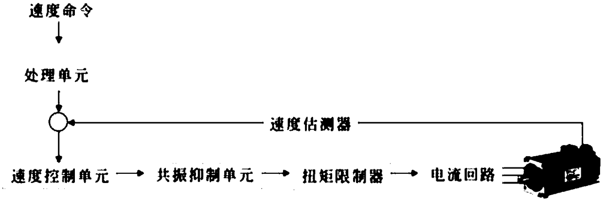
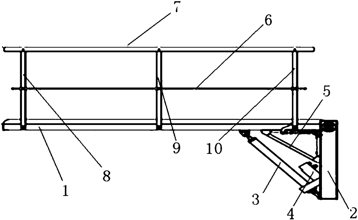
[0026] Please refer to Figure 1-Figure 5 , in a specific embodiment, the boarding bridge provided by the present invention includes a control device, and the control device makes the bridge body rise or fall through the driving device, and the driving device includes the electric cylinder 3 and drives the electric cylinder 3. The cylinder 3 works with a servo motor 4 with a brake. The servo motor 4 and the electric cylinder 3 are ...


PUM


Abstract

The invention discloses a boarding bridge comprising a control device. The control device enables a bridge body to rise or fall through a driving device, the driving device comprises an electric cylinder and a servo motor driving the electric cylinder to work and provided with a contracting brake, and the bridge body comprises a mounting frame. A bridge frame where bridge plates are laid is rotatably arranged on the mounting frame, one end of the electric cylinder is hinged to the bridge frame, and the other end of the electric cylinder is hinged to the mounting frame. The control device comprises a main controller, the main controller is electrically connected with a motor controller, a power source, a contactor and an operating keyboard, and the motor controller comprises a processing unit. The processing unit is sequentially electrically connected with a speed control unit and a speed evaluation unit, the speed control unit is sequentially connected with a resonance inhibition unit,a torque limiting unit and a current loop unit, and the speed evaluation unit and the current loop unit are electrically connected with the servo motor. In the structure, position accurate control can be achieved, operation is stable, the safety is high, meanwhile it is ensured that during operation, noise is small, pollution is avoided, and maintenance is easy.

Description

technical field [0001] The invention relates to the technical field of aircraft auxiliary equipment manufacturing, in particular to a boarding bridge. Background technique [0002] The boarding bridge is usually composed of several sections of retractable channel sockets, which can be extended to the door of the aircraft and docked with it when the aircraft is getting on and off the passengers, so that passengers can transfer between the aircraft parking place and the terminal building in the airport , and the aircraft models are different, the height of the aircraft door is also different, so it is necessary to use a lifting device to adjust the height of the passage. [0003] In the existing boarding bridge control system, PLC (programmable logic controller) is usually used as the main control element to control the lifting drive and travel drive of the boarding bridge. During the lifting control of the boarding bridge, the operator passes the command to the PLC by pressi...

Claims


Application Information

Patent Timeline
IPC IPC(8): B64F1/305
CPCB64F1/305B64F1/3055
Inventor 倪进宇陈伟吴晓娟白丹赵庆田竞
Owner 北京摩诘创新科技股份有限公司
Why Eureka
Try Eureka