Eureka AIR delivers breakthrough ideas for toughest innovation challenges, trusted by R&D personnel around the world.

Fire distribution structure of two-cavity direct injection burner

A burner and fire ring technology, applied in burners, gas fuel burners, combustion methods, etc., can solve problems such as difficulty in meeting first-level energy efficiency requirements, the structure of the inner fire cover has not been optimized, and it is difficult to ensure sufficient combustion, etc. Good fire adjustment effect, good air mixing effect and high combustion power effect

Pending Publication Date: 2018-07-17
GUANDDONG JIBAO ELECTRICAL APPLIANCE TECH CO LTD
View PDF1 Cites 0 Cited by
  • Summary
  • Abstract
  • Description
  • Claims
  • Application Information

AI Technical Summary

Problems solved by technology

[0003] The burner adopts direct injection to form mixed gas and air supply, which can improve the combustion efficiency and make the combustion more complete. However, the structure of the inner fire cover has not been optimized, and it is difficult to ensure sufficient combustion, that is, it is difficult to reach the first-class standard stipulated by the state. energy efficiency requirements

Method used


Image

  • Fire distribution structure of two-cavity direct injection burner
  • Fire distribution structure of two-cavity direct injection burner
  • Fire distribution structure of two-cavity direct injection burner

Examples


no. 1 example

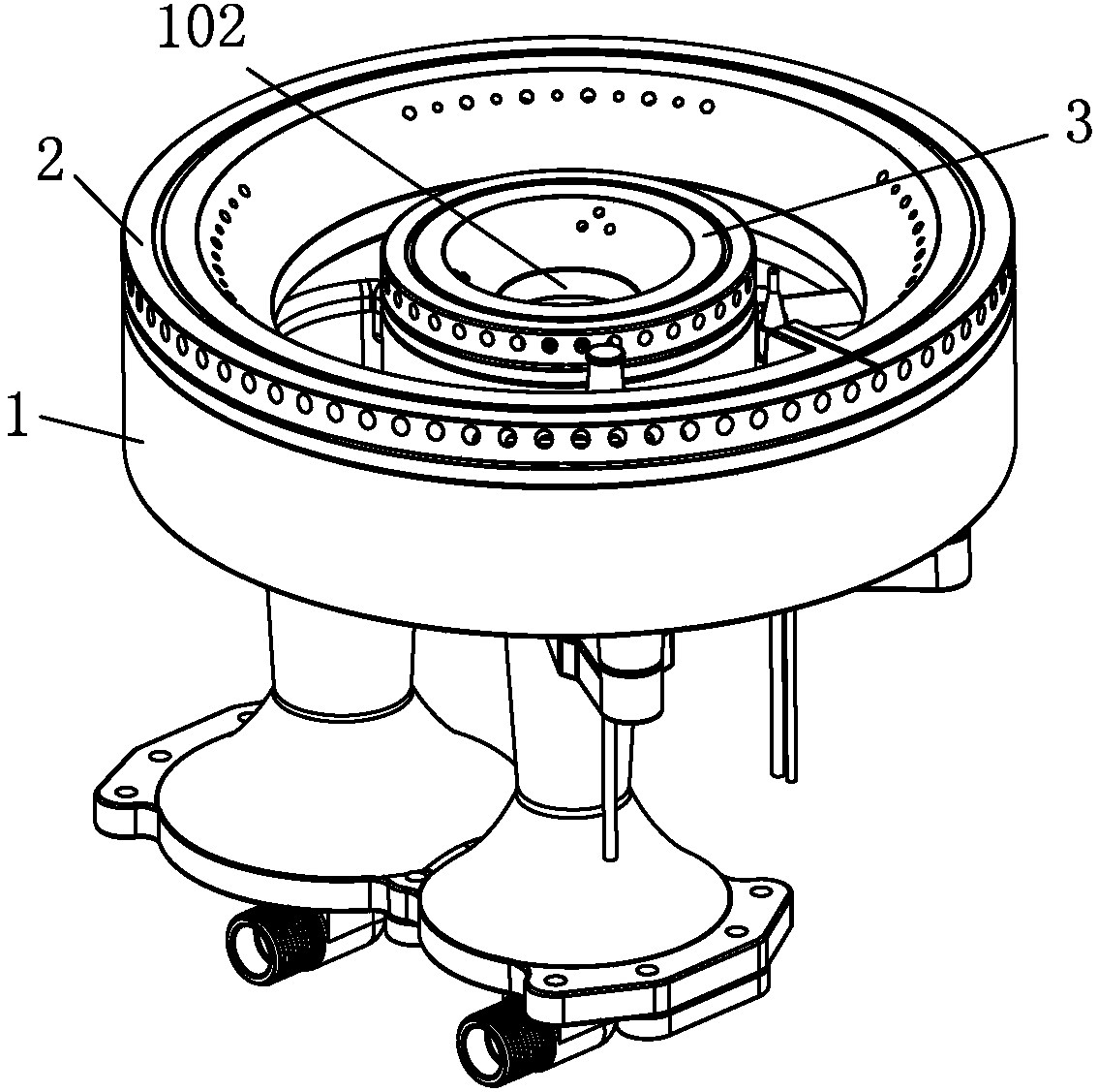
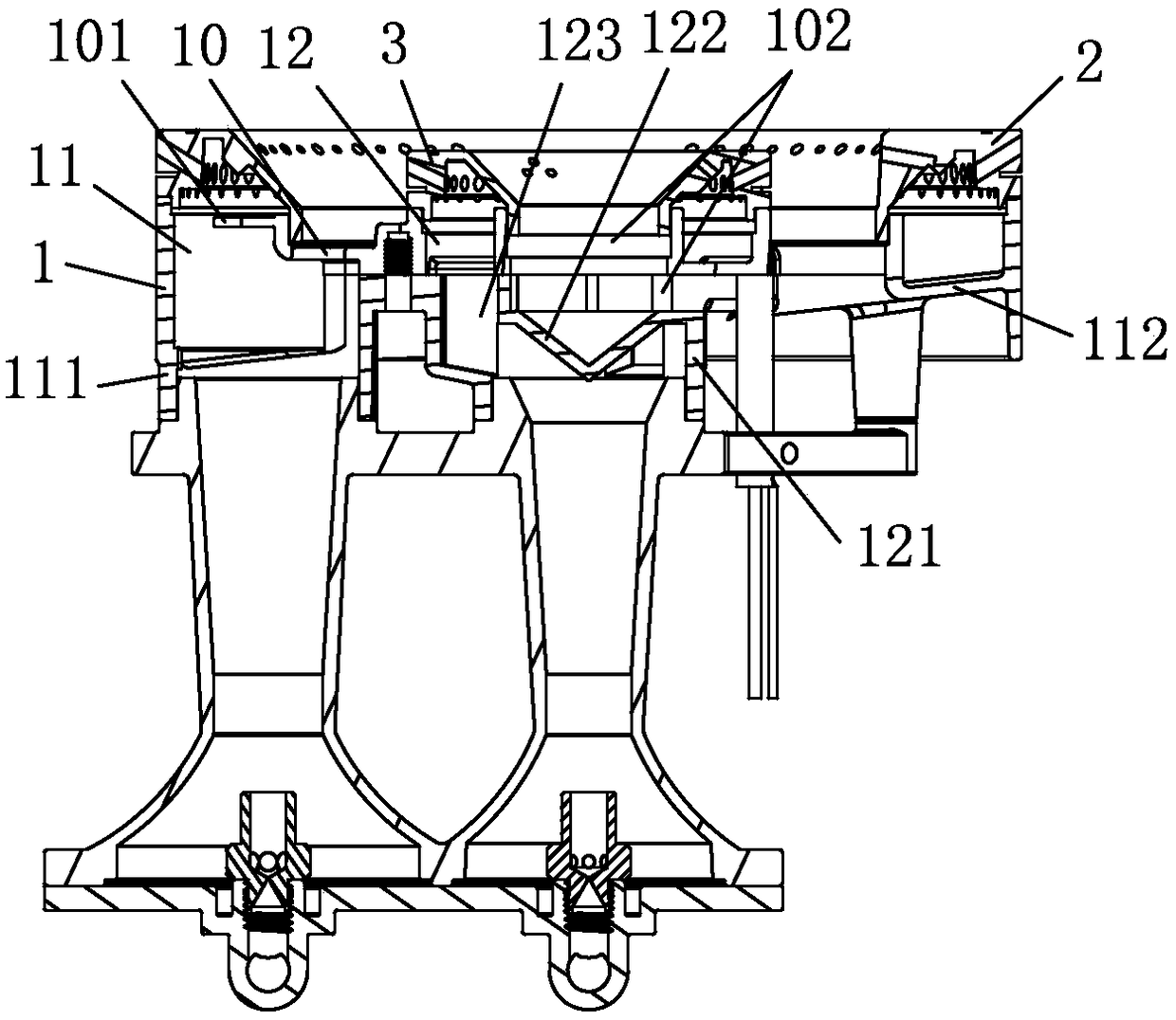
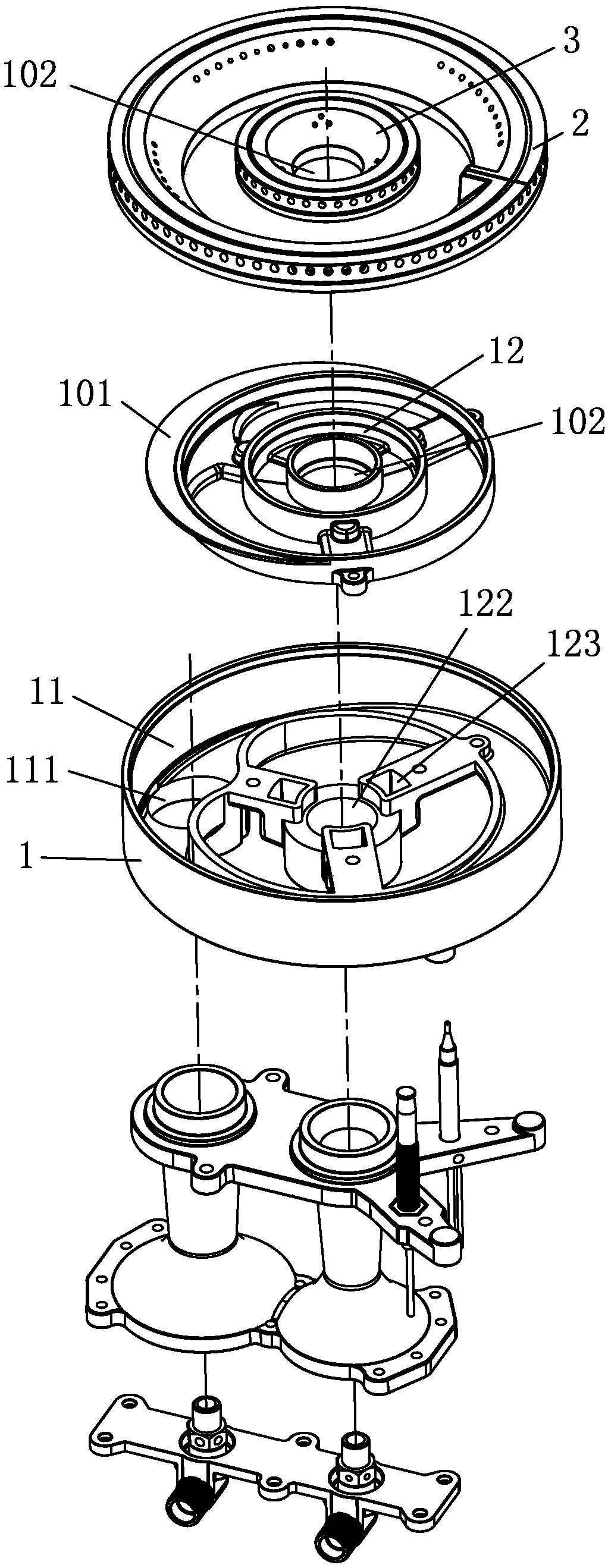
[0021] see Figure 1-4 , the fire distribution structure of the dual-chamber direct injection burner includes a fire cover seat 1 provided with an outer ring fire ring 11 and a central fire ring 12, and the outer ring fire ring 11 and the center fire ring 12 are covered with outer ring fire rings respectively. Cover 2 and center fire cover 3, the bottom of described fire cover seat 1 is provided with outer ring air inlet 111 corresponding to the position of outer ring fire ring 11, and outer ring air inlet 111 communicates with outer ring fire ring 11, and described fire The center of the bottom of the cover seat 1 is provided with a central air inlet 121, and the central air inlet 121 communicates with the central fire ring 12 through several central air inlet passages 123 arranged around it. The bottom of the central air inlet 121 is closed and the inside Corresponding to the junction of the central air inlet 121 and the central air inlet channel 123 on the bottom, there is ...


PUM


Abstract

The invention discloses a fire distribution structure of a two-cavity direct injection burner. The fire distribution structure comprises a burner cap seat which is provided with an external fire ringand a center fire ring; the external fire ring is connected with an external ring burner cap in a covered manner; the center fire ring is connected with a center burner cap in a covered manner; an external ring gas inlet is formed in the position, corresponding to the external fire ring, of the bottom of the burner cap seat; the external ring gas inlet communicates with the external fire ring; a center gas inlet is formed in the bottom center of the burner cap seat; the center gas inlet communicates with the center fire ring through a plurality of center gas inlet channels formed in the periphery of the center gas inlet; the bottom of the center gas inlet is closed; and an inverted-cone-shaped gas-distributing cone is arranged at the parts, corresponding to the connecting parts of the center gas inlet and the center gas inlet channels, of the inner bottom of the center gas inlet. The gas-distributing cone can allow a gas mixture of air entering from the center gas inlet and gas to generate turbulence, the air is mixed with the gas fully, the gas mixture is uniformly conveyed to the center gas inlet channels, the center fire ring and the center burner cap, the gas mixing effect of the gas mixture entering the center burner cap is good, and sufficient combustion can be guaranteed.

Description

technical field [0001] The invention relates to a flame distribution structure of a double-cavity direct-injection burner. Background technique [0002] Chinese Patent Document No. CN1900593A discloses a burner with balanced gas distribution, which includes a gas seat with an air mixing pipe at the bottom and an inner fire cover and an outer fire cover arranged above the gas seat. An outer ring air groove and an inner ring air groove are provided, a gas passage is provided between the inner ring air groove and the outer ring air groove, and several outer air mixing passages separated from the gas passage are arranged between two adjacent gas passages , there is an inner air mixing channel between each of the outer air mixing channels and the inner fire cover. [0003] The burner adopts direct injection to form mixed gas and air supply, which can improve the combustion efficiency and make the combustion more complete. However, the structure of the inner fire cover has not be...

Claims


Application Information

Patent Timeline
Patent Type & Authority Applications(China)
IPC IPC(8): F23D14/02F23D14/46F23D14/58F23D14/62
CPCF23D14/02F23D14/46F23D14/58F23D14/62
Inventor 胡志学韦贺木李恩明
Owner GUANDDONG JIBAO ELECTRICAL APPLIANCE TECH CO LTD
Why Eureka
Eureka Blog
Learn More