Mold testing method, device thereof and electronic equipment

A detection method and mold technology, applied in image data processing, instrumentation, calculation, etc., can solve problems such as mold damage, equipment production efficiency reduction, economic loss, etc.

Active Publication Date: 2018-07-17
BEIJING INSTITUTE OF TECHNOLOGYGY
View PDF7 Cites 7 Cited by
  • Summary
  • Abstract
  • Description
  • Claims
  • Application Information

AI Technical Summary

Problems solved by technology

Once a problem occurs, the workpiece will be damaged, the machine will stop production, and the mold will be damaged, causing major economic losses and reducing the production efficiency of the equipment.

Method used


Image

  • Mold testing method, device thereof and electronic equipment
  • Mold testing method, device thereof and electronic equipment
  • Mold testing method, device thereof and electronic equipment

Examples


no. 1 example

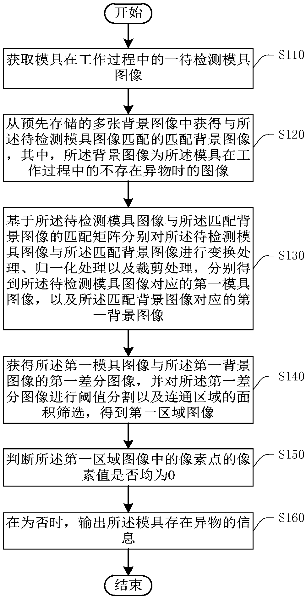
[0030] like figure 2 A flow chart provided by an embodiment of the present invention is shown. See figure 2 , the mold detection method includes:

[0031] Step S110: Obtain an image of the mold to be inspected during the working process of the mold.

[0032] In the embodiment of the present invention, the mold detection method can be applied to detect whether there are foreign objects in a dynamically working mold.

[0033]During the working process of the mold, the image of the mold can be collected in real time through the camera. In addition, the camera can collect the image of the mold during work according to a certain frequency. After the image of the mold is collected, it is judged whether there is foreign matter in the mold according to the collected image. The image collected above is the image of the mold to be inspected during the working process of the acquired mold.

[0034] Step S120: Obtain a matching background image that matches the image of the mold to...

no. 2 example

[0086] The second embodiment of the present invention provides a mold inspection device 200, please refer to Figure 5 , the mold inspection device 200 includes: an image acquisition module 210 , an image matching module 220 , a first image processing module 230 , a second image processing module 240 , a pixel value judgment module 250 and an execution module 260 . Wherein, the image acquisition module 210 is used to acquire an image of the mold to be inspected during the working process of the mold; the image matching module 220 is used to obtain an image matching the image of the mold to be inspected from a plurality of pre-stored background images. matching the background image, wherein the background image is an image of the mold in the working process when there is no foreign matter; the first image processing module 230 is used for matching the background image based on the mold image to be detected The matching matrix performs transformation processing, normalization pr...

no. 3 example

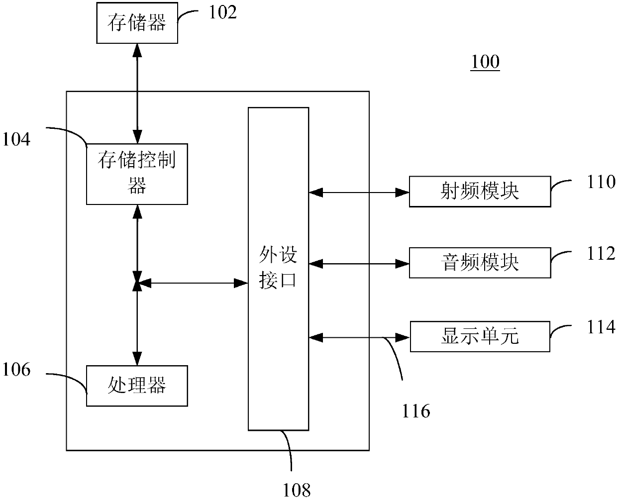
[0095] The third embodiment of the present invention provides an electronic device 100, please refer to figure 1 , the electronic device 100 includes a memory 102 and a processor 106, the memory 102 stores computer instructions, and when the computer instructions are read and executed by the processor 106, the processor 106 is made to execute the first embodiment of the present invention. The mold detection method that embodiment provides.


PUM


Abstract

The invention provides a mold testing method, a device thereof and electronic equipment, wherein the method, the device thereof and the electronic equipment relate to the field of mold testing technology. The mold testing method comprises the steps of acquiring a matched background image which matches a to-be-tested mold image in a plurality of prestored background image, wherein the background image is the image on the condition of no foreign matter in a working process; performing transformation processing, normalization processing and cutting processing on the to-be-tested mold image and the matched background image based on the matching matrix of the to-be-tested mold image and the matched background image, and obtaining a first mold image and a first background image; obtaining a first differential image of the first mold image and the first background image, performing threshold segmentation on the first differential image and communicating area screening, and obtaining a first area image; determining whether the pixel value of pixels in the first area image is zero; and if not, outputting information that the foreign matter exists in the mold. The mold testing method can realize automatic testing for the foreign matter of the mold.

Description

technical field [0001] The invention relates to the technical field of mold detection, in particular to a mold detection method, device and electronic equipment. Background technique [0002] In recent years, with the advancement of mold design and manufacturing technology, as well as higher requirements for process automation, high precision, high efficiency and long life, various molds have been vigorously developed. They are used in automobiles, aerospace, instruments, household appliances, It is widely used in the production of products in many fields such as electronics, communications, military industry and daily necessities. For example, progressive die is an important stamping equipment for semi-automation and automation, and it is an advanced mold structure to ensure stable processing quality. [0003] In actual production, manual monitoring of the internal state of the mold is mostly adopted. The operator mainly observes the internal condition of the mold visually...

Claims


Application Information

Patent Timeline
Patent Type & Authority Applications(China)
IPC IPC(8): G06T7/00G06T7/11G06T7/136G06T7/194
CPCG06T7/0008G06T7/11G06T7/136G06T7/194
Inventor 孟凡武王琦李珂敬黄志鹏
Owner BEIJING INSTITUTE OF TECHNOLOGYGY
Why Eureka
Try Eureka