

Blade arrangement and clamping member for hand-held power tools
A power tool, hand-held technology, applied in the field of clamping components, which can solve the problems of connection wear and looseness
- Summary
- Abstract
- Description
- Claims
- Application Information
AI Technical Summary
Problems solved by technology
Method used
Image

Examples
Embodiment Construction
[0038] Aspects of the invention will now be described more fully. Like reference numerals refer to like elements throughout. Well-known functions or constructions are not necessarily described in detail for brevity and / or clarity.
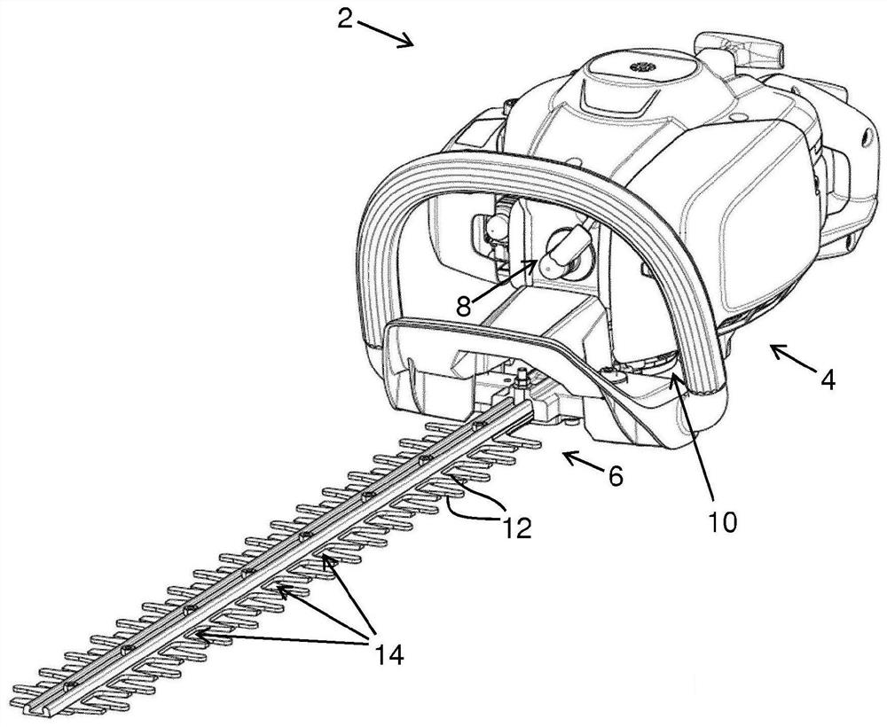
[0039] figure 1 A hand-held power tool 2 according to an embodiment is shown. According to these embodiments, the handheld power tool is a hedge trimmer 2 . However, according to alternative embodiments, the hand-held power tool 2 may be any hand-held power tool comprising a pair of blade arrangements, at least one of which is a blade arrangement as discussed herein.
[0040] The hand-held power tool 2 includes a drive unit 4 and a pair of blade units 6 . Drive 4 includes, for example, an internal combustion engine 8 and a transmission 10 . The transmission 10 is configured for converting the rotational motion caused by the internal combustion engine 8 into a linear reciprocating motion of each blade arrangement 6 of a pair of blade arrangemen...
PUM
 Abstract
Description
Claims
Application Information