Grate plate for a grate cooler

A cooler and grate plate technology, which is applied in the direction of processing discharged materials, furnaces, lighting and heating equipment, etc., can solve the problems of unfavorable, increased flow resistance, pressure loss, and insufficient reduction, and achieve simple structure and improved Effect of air inflow velocity, reduction of flow resistance or pressure loss

Inactive Publication Date: 2018-07-17
KHD HUMBOLDT WEDAG GMBH
View PDF4 Cites 0 Cited by
  • Summary
  • Abstract
  • Description
  • Claims
  • Application Information

AI Technical Summary

Problems solved by technology

In this case, this significantly increases the flow resistance or the strong pressure loss in the cooling air flow, which is not only expensive to compensate, but also in the overall supply of air to the grate cooler or the corresponding grate plate. Disadvantageously, in uncovered, less intense compression areas, (vertical) temperature gradients develop in the bulk material bed, which do not lead to optimal effective and uniform cooling of the conveyed loose material
Furthermore, with this necessitating an increased air velocity in the conveying area, there is a disadvantageous increase in the risk of penetration or the formation of cold aisles
Furthermore, it is also disadvantageous that cooling on the bottom of the groove in the covered area by means of cooling air through the usual openings leading into the underside of the grate is generally not sufficient to sufficiently reduce the especially temperature-dependent wear

Method used


Image

  • Grate plate for a grate cooler
  • Grate plate for a grate cooler
  • Grate plate for a grate cooler

Examples


Embodiment Construction

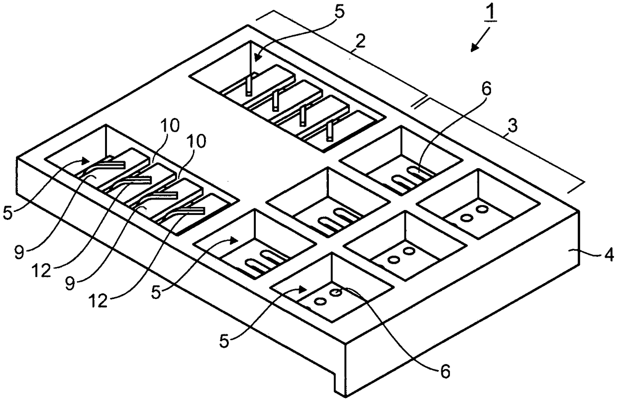
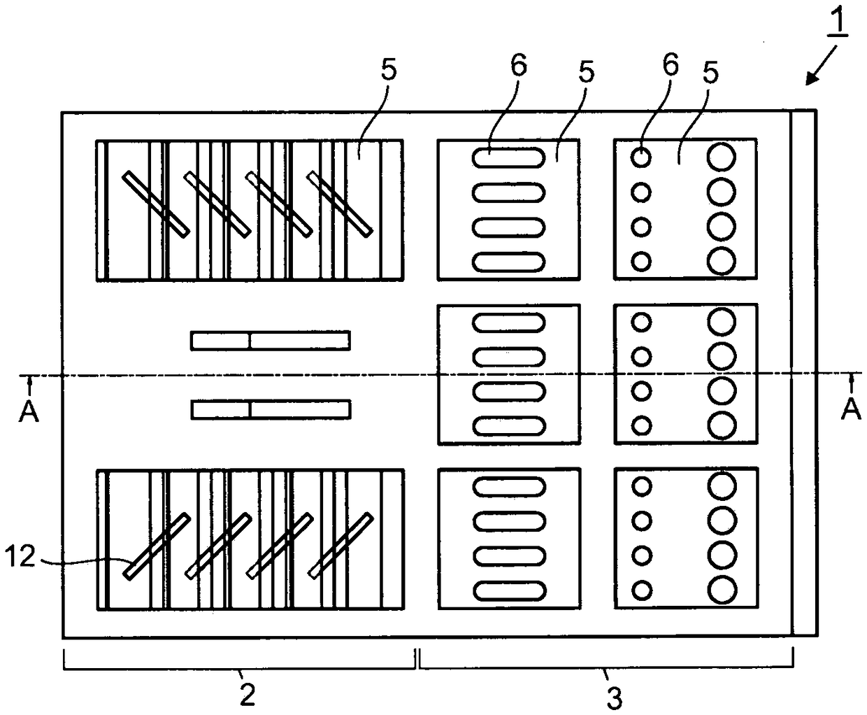
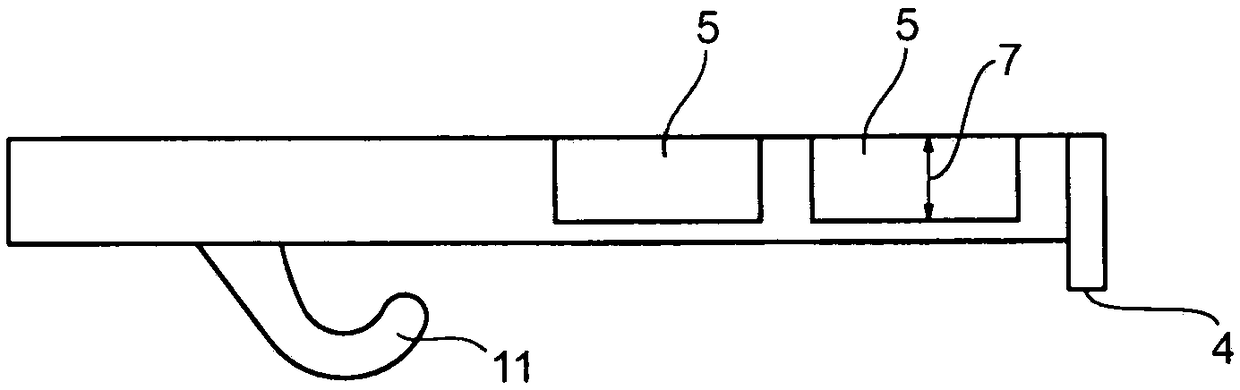
[0028] exist figure 1 shows a grate plate 1 according to the invention, the upper side of which is composed of a first working area (covered area 2 ) and a second working area (uncovered area 3 ). When the grate 1 is installed in a grate cooler, hot bulk material (not shown) falls from the grate steps above the grate onto the cover area 2 and from there through the grate 1 above it The oscillating to-and-fro movement of is pushed into the uncovered area 3 . exist Figure 4 in (and in Figure 5 Middle) shows the interrelationship of two such stepped grate plates 1 . In this case, movably mounted grate rows alternate with statically fixed grate rows on successive steps. For example, in the illustration the upper grate 1 can be assumed to be movable and carry out an oscillating drive movement, while the lower grate 1 is stationary. In this way, loose material (not shown) falling from the upper grate 1 into the covering area 2 of the lower grate 1 is pushed into the lower gra...


PUM


Abstract

The invention relates to a grate plate (1) for use in a grate cooler for hot bulk material, comprising a first working region (2) which is alternatingly covered by a further grate plate (1) during useof the grate plate (1) in a grate cooler, and which has at least one bag (5) for holding bulk material as an autogenous wear protection layer, and comprising a second working region (3) which is notcovered by a further grate plate (1) during use of the grate plate (1), and which has at least one bag (5) for holding bulk material as an autogenous wear protection layer and having at least one opening (6) leading to the underside of the grate plate (1) for the introduction of cooling air. According to the invention, the height (8) of the bags (5) in the covering region (2) is smaller than the height (7) of the bags (5) in the covering-free region (3), and the base of the bags (5) in the covering region (2) is respectively formed by multiple segments (9), the surfaces of which function as contact surfaces for bulk material and between which gap-like cooling air channels (10) are formed, wherein the openings of the cooling air channels (10) provided between the upper sides of the segments(9) are each oriented at a certain angle to the vertical, such that a respective acute angle occurs between the conveying direction and the direction of the cooling air flow via these openings.

Description

technical field [0001] The invention relates to a grate for use in a grate cooler for hot bulk material, the grate having a second grate which is alternately covered by at least one further grate when the grate is installed in the grate cooler A working area (covered area), wherein the covered area has at least one groove for retaining bulk material as an autogenous wear protection layer, and the grate has a grate that is not affected by other components when the grate is installed in the grate cooler The second working area (uncovered area) covered by the grate plate, wherein the uncovered area has at least one groove for retaining loose material as a self-generated wear protection layer, the groove has at least one opening to the grate Openings on the underside of the plate for the introduction of cooling air. Background technique [0002] Grate coolers are used to cool hot bulk materials such as burnt mineral material or cement clinker discharged from a rotary tube furna...

Claims


Application Information

Patent Timeline
Patent Type & Authority Applications(China)
IPC IPC(8): F27D15/02
CPCF27D15/0213F27D15/022F27D2015/0233
Inventor W·科罗特茨基K·岑克尔R·萨克塞纳
Owner KHD HUMBOLDT WEDAG GMBH
Why Eureka
Try Eureka