
Touch screen device

A touch screen and frame technology, applied in instruments, mechanical mode conversion, computing, etc., can solve the problems of uneven vibration force, reduced installation space, size and number, and achieve the effect of increasing vibration force

Inactive Publication Date: 2018-07-17
MODA INNOCHIPS CO LTD
View PDF5 Cites 6 Cited by
  • Summary
  • Abstract
  • Description
  • Claims
  • Application Information

AI Technical Summary

Problems solved by technology

However, this method has a problem in the related art that the vibration force is not uniform across the touch screen panel
In addition, since the installation space of the piezoelectric vibration device is reduced due to the tendency of the area of ​​the touch screen panel to decrease while the number of modules integrated in the board is increased, the size and number of the piezoelectric vibration device are reduced , and thus the vibration may be weak

Method used


Image

  • Touch screen device
  • Touch screen device
  • Touch screen device

Examples


Embodiment Construction

[0034] Hereinafter, various embodiments will be explained in more detail with reference to the accompanying drawings. However, this invention may be embodied in different forms and should not be construed as limited to only the embodiments set forth herein. Rather, these embodiments are provided so that this disclosure will be thorough and complete, and will fully convey the scope of the invention to those skilled in the art.

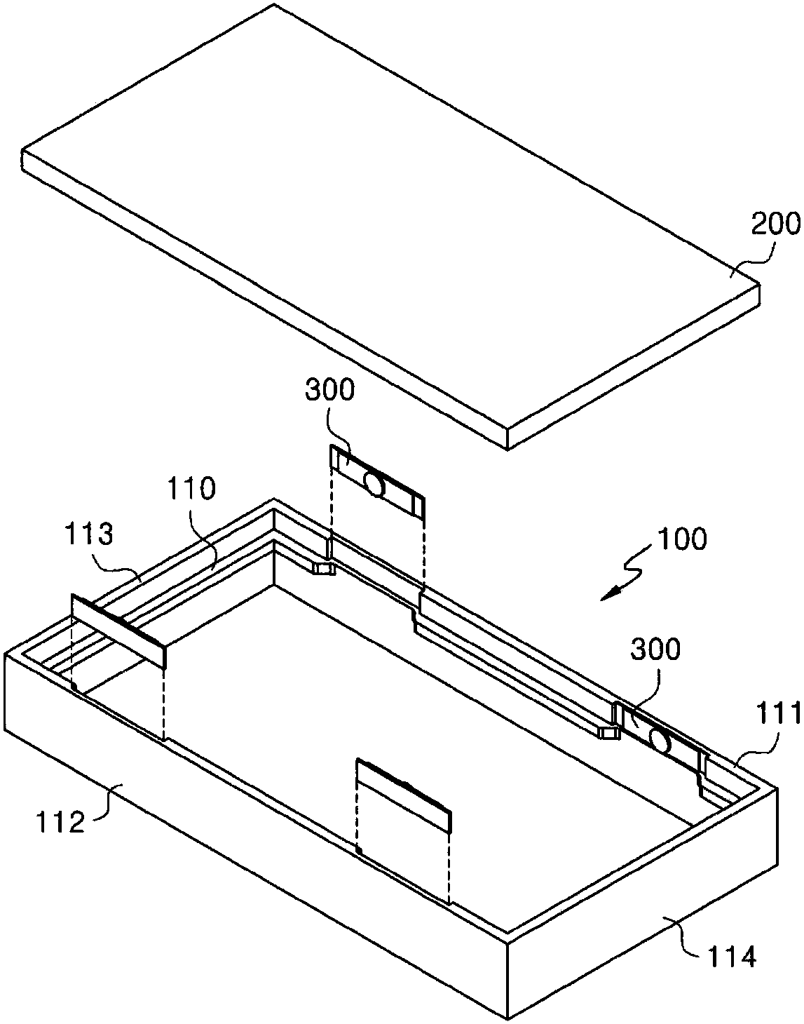
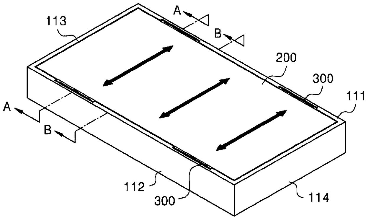
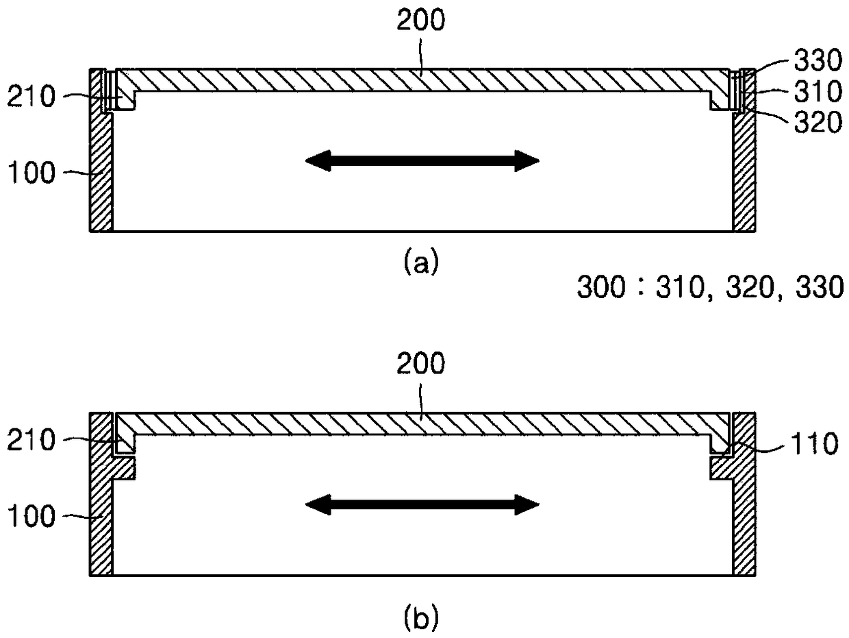
[0035] figure 1 is an exploded perspective view of a touch screen device according to an exemplary embodiment, figure 2 is the assembled stereogram, and image 3 is an assembled cross-sectional view. in addition, Figure 4 It is a perspective view of a piezoelectric vibrating member used in a touch panel device. here, image 3 (a) and image 3 (b) are respectively along figure 2 Sectional views taken along lines A-A and B-B shown.

[0036] refer to Figure 1 to Figure 3 , The touch screen device according to an exemplary embodiment may inclu...


PUM


Abstract

The present invention presents a touch screen device which comprises: a frame; a touch screen panel arranged in the frame; and a piezoelectric vibration member arranged between the frame and the touchscreen panel, wherein the piezoelectric vibration member vibrates in a horizontal direction of the touch screen panel.

Description

technical field [0001] The present invention relates to a touch screen device, and more particularly to a touch screen device in which haptic feedback may exist. Background technique [0002] A liquid crystal display (LCD) has been generally used in various information transmission and audio video (Audio Video, AV) systems. In addition, the touch screen has been applied to the liquid crystal display to facilitate the interface with the driver. The touch screen is designed so that when the screen is touched by using a finger or a stylus, instructions can be executed after detecting a touched portion or a position where a cursor moves. [0003] In addition, the vibration generating device is applied to the touch screen and thereby, enables the user to instantaneously sense feedback vibration for the user's touch input. That is, the vibration generating device disposed in the touch screen device can be used as a means for providing tactile feedback to the user's touch through...

Claims


Application Information

Patent Timeline
Patent Type & Authority Applications(China)
IPC IPC(8): G06F3/041G06F3/01
CPCG06F2203/04103G06F3/016H10N30/20G06F3/0412
Inventor 朴城撤金永述李釉珩朴完
Owner MODA INNOCHIPS CO LTD
Learn More