
Filler ring applicable to kitchen oil fume purification and filler

A technology for oil fume purification and packing ring, which is applied in chemical instruments and methods, chemical/physical processes, chemical/physical/physical chemical processes, etc. It can improve the oil fume removal rate, reduce the loss of air volume and air pressure, and improve the permeability.

Active Publication Date: 2018-07-20
深圳市高德威技术有限公司
View PDF10 Cites 2 Cited by
  • Summary
  • Abstract
  • Description
  • Claims
  • Application Information

AI Technical Summary

Problems solved by technology

In the field of oil fume purification, the filler acts as a purification core with a volume of about 0.1 m 3 , the air flow is about 5000 m 3 / h, the flow rate is fast, and the traditional ring packing cannot be fully applied to this working condition
[0007] Among the existing ring packings, they have good hydrodynamic properties, moderate pressure drop, high flux, stable mass transfer performance and high efficiency, and are more suitable for several ring packing pairs in the mass transfer separation process of clean and alkaline corrosive fluids. The influence of pressure resistance and removal rate is shown in Table 1. Although the flat ring packing has a relatively high specific surface area, its porosity is small, resulting in high system operation resistance, high noise, and large air volume loss, which reduces the working efficiency of the equipment.
Due to the special structure of the conjugate ring and the saddle ring, the two-to-two contact in the equipment is all point contact, and the pressure resistance is small. However, it cannot be fully applied in the oil fume purification system that requires a certain resistance to control droplets, which will cause The droplet problem at the end of the equipment, if the use must reduce the amount of foaming, it will seriously affect the effect of oil fume purification; and the specific surface area of ​​the two ring packings is low, the ability to effectively intercept oil fume is weak, and it cannot meet the needs of environmental protection.

Method used


Image

  • Filler ring applicable to kitchen oil fume purification and filler
  • Filler ring applicable to kitchen oil fume purification and filler
  • Filler ring applicable to kitchen oil fume purification and filler

Examples


Embodiment Construction

[0027] The technical solutions in the embodiments of the present invention are clearly and completely described below in conjunction with the accompanying drawings in the embodiments of the present invention. Obviously, the described embodiments are only part of the embodiments of the present invention, not all of them. Based on the embodiments of the present invention, all other embodiments obtained by persons of ordinary skill in the art without making creative efforts belong to the protection scope of the present invention.

[0028] In the following description, a lot of specific details are set forth in order to fully understand the present invention, but the present invention can also be implemented in other ways different from those described here, and those skilled in the art can do it without departing from the meaning of the present invention. By analogy, the present invention is therefore not limited to the specific examples disclosed below.

[0029] Such as figure ...


PUM

PropertyMeasurementUnit
thicknessaaaaaaaaaa
aspect ratioaaaaaaaaaa

Abstract

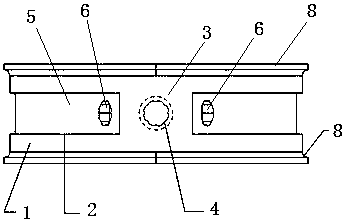
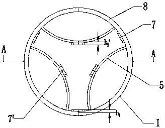
The invention discloses a filler ring applicable to kitchen oil fume purification and filler. The filler ring comprises a circular main body, several rectangular windows are formed in the wall face ofthe circular main body, the spacing of every two adjacent rectangular windows is the same, a vertical beam is formed between every two adjacent rectangular windows, a first stretching hole is formedin each vertical beam, an arc fin which bends inwards is arranged on the inner wall, opposite to each rectangular window, of the circular main body, a second stretching hole is formed in each arc fin,and the first stretching holes are opposite to the second stretching holes. The filler has the advantages that the specific area is large, the gap rate is high, the piezoresistance is small, the noise is small, and the oil fume removing rate is high.

Description

technical field [0001] The invention relates to the technical field of oil fume purification devices, in particular to a packing ring and packing suitable for kitchen oil fume purification. Background technique [0002] With the rapid development of the economy and the rise of the tertiary industry, the urban catering service industry has developed rapidly. While improving people's living standards, various restaurants all over the urban area have also brought increasingly serious environmental protection problems. The untreated oily smoke from the catering industry is directly emitted, which has caused dissatisfaction and even complaints from urban residents. Therefore, the state attaches great importance to the control of oily fumes outside kitchens in the catering service industry, and has gradually issued corresponding laws and regulations to limit the emission of oily fumes. At present, there are some technical measures and corresponding equipment at home and abroad f...

Claims


Application Information

Patent Timeline
Patent Type & Authority Applications(China)
IPC IPC(8): B01J19/30B01D53/00B01D46/30
CPCB01D46/30B01D53/00B01J19/30B01J2219/30296
Inventor 赵艳需梅倩
Owner 深圳市高德威技术有限公司
Learn More