Use of shaped bodies having catalytic properties as reactor internals

a technology of catalytic properties and shaped bodies, which is applied in the direction of catalyst activation/preparation, metal/metal-oxide/metal-hydroxide catalysts, and additive manufacturing with solids and fluids. it can solve the problems of high pressure drop in the reactor, catalyst is exposed to the reactants only very unevenly, and the removal and installation of the shaped bodies required for the replacement of the catalyst can be very complicated

Inactive Publication Date: 2012-02-21
BASF SE
View PDF16 Cites 45 Cited by
  • Summary
  • Abstract
  • Description
  • Claims
  • Application Information

AI Technical Summary

Benefits of technology

[0014]It was an object of the present invention to improve the use of catalysts in heterogeneously catalyzed chemical reactions and to avoid the abovementioned disadvantages of known catalysts. When the catalysts are used, it should be possible to achieve a low pressure drop compared to beds, preferably very high transverse mixing compared to also only a little backmixing counter to the flow direction and sufficiently high mass transfer and heat transport, including radial heat transport.
[0022]According to the invention, the object is therefore achieved by the use of shaped bodies which have catalytic properties and whose geometry is optimized for the respective flow and reaction conditions in the reactor. The reactor internals can be tailored to the required reaction conditions, which is not possible by means of conventional techniques such as extrusion or injection molding. The advantage of the rapid prototyping technology compared to these conventional manufacturing techniques is that theoretically any desired geometry, including complex components having, for example, hollow spaces or microchannels, can be converted with the aid of computer control using a CAD data set into the corresponding three-dimensional component without a prior production of negative casting molds, without cutting, milling, grinding, soldering, etc. This makes it possible to produce reactor internals which, owing to their optimized geometry, offer advantages over conventional reactor internals in terms of mass transfer and heat transport in chemical reactions. This process intensification results in higher yields, conversions and selectivities and reliable reaction conditions and can, as a result of reduced apparatus sizes or reduced amounts of catalyst, lead to cost savings for existing or new processes in the chemical industry.

Problems solved by technology

However, this way of using catalysts has the disadvantage that the beds described generally lead to a high pressure drop in the reactor.
In addition, formation of channels or formation of zones having stagnating gas and / or liquid movement can easily occur, so that the catalyst is exposed to the reactants only very unevenly.
Furthermore, the removal and installation of the shaped bodies which is required when the catalyst is replaced can be very complicated, for example in the case of shell-and-tube reactors or salt bath reactors having a large number of tubes.
A disadvantage is that, owing to the increased porosity of the packing, a relatively large reactor volume is required and the internals offer a large metallic surface area.
Additional metal in the form of the packing is required, which leads to increased materials costs.
Furthermore, corrosion can occur and metal ions can be dissolved.
The use of these, packings has the disadvantage that in processes in which the catalyst is surrounded by a gas / liquid mixture, the appropriate liquid trickle density has to be adhered to exactly, which proves to be difficult in practice.
This leads, when liquid flows are too high, to flow over the catalyst pouches, while a liquid flow which is too low leads to “drying out” of the catalyst.
This can in practice lead to inhomogeneous distribution of concentrations, temperatures and flow velocities and also unsatisfactory radial heat dispersion.
The low ratio of catalyst (support) space mass to reactor volume is usually a disadvantage.
Despite the disadvantages described, the physical form of a monolith has become established in exhaust gas catalysts because of a lack of better alternatives for motor vehicles.
The disadvantage of this production process is the additional process step in which the negative mold is firstly produced before final production occurs in the form of casting.
The reactor internals can be tailored to the required reaction conditions, which is not possible by means of conventional techniques such as extrusion or injection molding.

Method used


Image

  • Use of shaped bodies having catalytic properties as reactor internals
  • Use of shaped bodies having catalytic properties as reactor internals

Examples


example 1

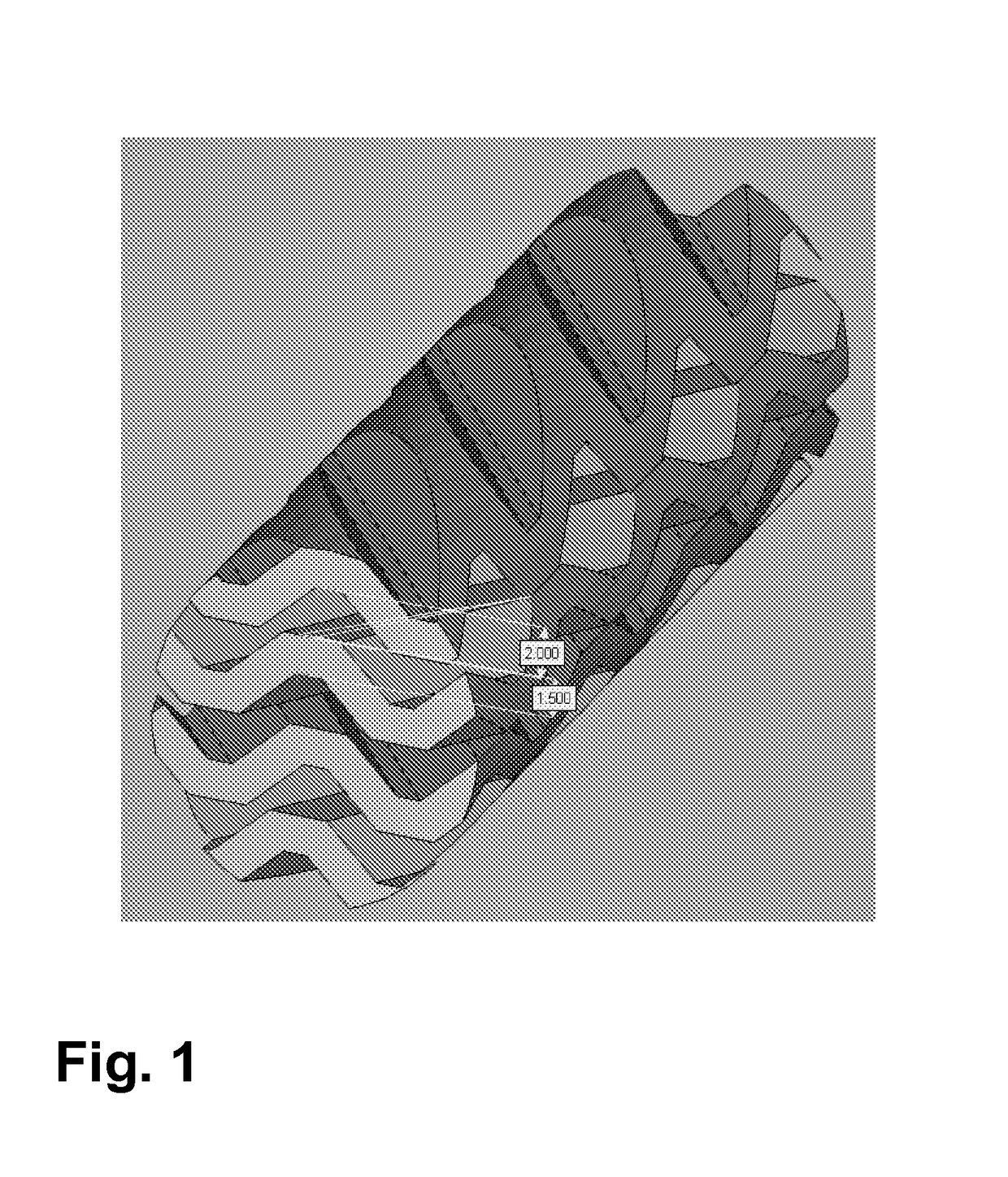
[0084]A three-dimensionally structured “cross-channel structure” as shown in FIG. 1 was produced from α-Al2O3. The length is 50 mm and the diameter is 14 mm.

[0085]The basis for the body is granular aluminum oxide CT 3000 SDP (from Almatis, 67065 Ludwigshafen) which is mixed with a solid binder xanthan, 200 mesh (from König & Wiegand, 40472 Düsseldorf) by means of a Turbula mixer (Willy A. Bachofen A G, 4058 Basel, Switzerland). The proportion of solid binder is 10% by weight, based on aluminum oxide. The three-dimensional printing was carried out by means of a Z-Printer 310 (Z-Corporation, Burlington, Mass. 01803, USA) using a water-based binder solution ZB 54 (Z-Corporation, Burlington, Mass. 01803, USA). 2% by weight of the liquid binder was used. After printing, the parts were firstly dried at 60° C. for 8 hours and then blown free by means of compressed air. Ceramic firing was carried out at 1600° C. with a hold time of 2 hours.

example 2

[0086]3.12 g of Bi(NO3)3.5H2O together with 3.36 g of Pd(NO3)2.2H2O and 48.6 mg of Co(NO3)2.6H2O are placed in a glass beaker. 18.17 g of distilled water and 9.08 g of concentrated nitric acid are added and the total mixture is stirred for 1 hour. Seven of the shaped Al2O3 bodies produced by rapid prototyping in example 1 and having a total mass of 42.8 g are placed in a Petri dish and the solution of the metal nitrates is added. The shapes are turned in the solution every 30 minutes and taken from the solution after 3 hours. The shapes are subsequently dried (120° C. for 4 hours) and calcined (heating at 2 K / min to 500° C., held at 500° C. for 10 hours). This gave 7 shapes having a total weight of 44.0 g and comprising 1.4% of Bi, 1.4% of Pd and 0.01% of Co.

example 3

[0088]50 ml of catalyst are installed in a salt bath reactor; a 10 ml layer of steatite is present as inert material at the top and at the bottom. The catalyst is brought to a temperature of 350° C. 120 standard l / h of nitrogen and 35 standard l / h of air are firstly passed over the catalyst, 15 minutes later 32.5 g / h of water are additionally added and a further 15 minutes later 22.4 g / h of cyclohexanone are added. The outputs are collected and the content of the desired reaction product cyclohexenone is determined by gas chromatography. The following table shows the results for the catalysts from example 2 and from comparative example 2 for three different temperatures.

[0089]

Conversion / mcat / gTemp. / ° C.%Selectivity / %Yield / %Example 23235059.659.435.437065.151.533.539068.443.329.6Comparative4835048.631.715.4example 237048.129.714.339051.025.212.8Conversion = conversion of cyclohexanoneSelectivity = selectivity to cyclohexenoneYield = yield of cyclohexenone

[0090]Despite a lower catalys...


PUM

PropertyMeasurementUnit
particle sizeaaaaaaaaaa
temperaturesaaaaaaaaaa

Abstract

Shaped bodies having catalytic properties which can be obtained by a process comprising the steps:a) production of a shaped body by means of a powder-based rapid prototyping process,b) if appropriate, a heat treatment of the shaped body,c) if appropriate, application of at least one catalytically active component to the shaped body,d) if appropriate, a further heat treatment,where steps b), c) and / or d) can be carried out a number of times,are used as reactor internals in heterogeneously catalyzed chemical reactions.

Description

CROSS REFERENCE TO RELATED APPLICATIONS[0001]This application is a National Phase filing under 35 U.S.C. §371 of PCT / EP2008 / 062956 filed Sep. 26, 2008, which claims priority to Patent Application No. 07118050.9, filed in Europe on Oct. 8, 2007. The entire contents of each of the above-applications are incorporated herein by reference.[0002]The invention relates to the use of shaped bodies having catalytic properties as reactor internals in heterogeneously catalyzed chemical reactions.BACKGROUND TO THE INVENTION[0003]Heterogeneous catalysis plays a central role in the modern chemical industry. Heterogeneous catalysts frequently comprise metals and / or metal oxides with whose surface the reactants in the reaction to be catalyzed interact. Apart from the nature of this interaction, the transport of the reactants to the active sites of the surface and the removal of the products from the surface play a critical role. In addition, the heat of reaction liberated has to be removed as quickl...

Claims


Application Information

Patent Timeline
Patent Type & Authority Patents(United States)
IPC IPC(8): B01J31/00B01J21/00B28B5/00B28B3/00C04B35/64C04B33/36C04B33/32B29C71/00B29C69/00B29C65/00B28B1/00B29B17/00B29C63/00
CPCB01J8/067B01J19/2485B01J19/30B01J19/32B01J23/8973B01J35/026B01J35/04B01J37/0201C04B35/111C04B35/14B01J21/04B01J2219/30288B01J2219/30416B01J2219/30475B01J2219/3085C04B2235/6026C04B2235/606C04B2235/95Y10S502/525Y10S502/524B33Y80/00B29C64/165B33Y70/00
Inventor KASHANI-SHIRAZI, NAWIDWLOKA, VERONIKAGERLINGER, WOLFGANGSCHMIDT, ANDREAHEINEN, KERSTINKOLLENBERG, WOLFGANG
Owner BASF SE
Why Eureka
Try Eureka