A LED linear lamp lampshade glue device
A technology of LED line lights and gluing devices, which is applied to the device and coating of the surface coating liquid, which can solve the problems of poor gluing effect, slow gluing speed, and poor adhesion of glass
- Summary
- Abstract
- Description
- Claims
- Application Information
AI Technical Summary
Problems solved by technology
Method used
Image
Examples
Embodiment 1
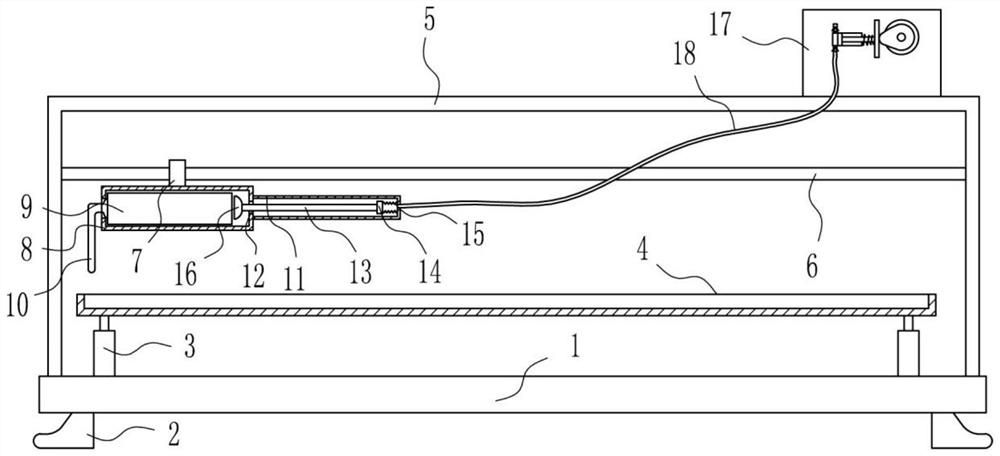
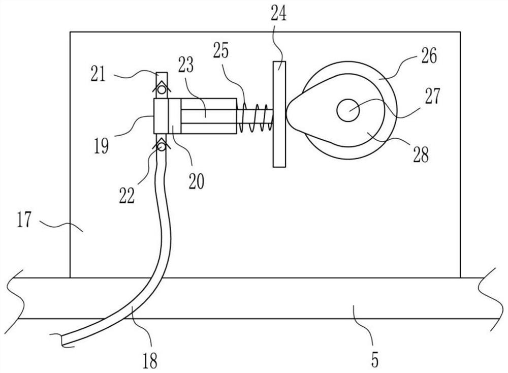
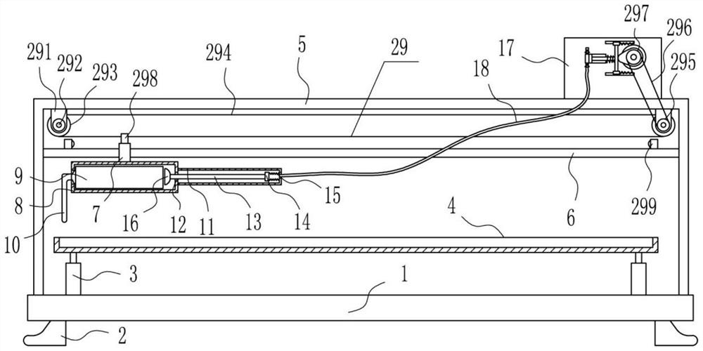
[0022] A lampshade gluing device for LED line lights, such as Figure 1-5 As shown, it includes bottom plate 1, outrigger 2, cylinder 3, placement frame 4, n-shaped frame 5, cross bar 6, sliding sleeve 7, placement pipe 8, rubber outlet pipe 10, housing 11, movable rod 13, fixed block 14. First spring 15, push block 16, vertical plate 17, air outlet pipe 18, compression cylinder 19, piston 20, intake pipe 21, one-way valve 22, slide rod 23, contact plate 24, second spring 25, motor 26 , rotating rod 27 and cam 28, base plate 1 bottom left and right sides symmetrical formula is installed with supporting leg 2, base plate 1 top left and right sides symmetrical formula is installed with cylinder 3, is installed between the telescoping rods of left and right sides cylinder 3 Frame 4, an n-shaped frame 5 is installed on the top of the bottom plate 1, and the placement frame 4 is located in the n-shaped frame 5. A crossbar 6 is installed between the upper left side surface and the upp...
Embodiment 2
[0024] A lampshade gluing device for LED line lights, such as Figure 1-5 As shown, it includes bottom plate 1, outrigger 2, cylinder 3, placement frame 4, n-shaped frame 5, cross bar 6, sliding sleeve 7, placement pipe 8, rubber outlet pipe 10, housing 11, movable rod 13, fixed block 14. First spring 15, push block 16, vertical plate 17, air outlet pipe 18, compression cylinder 19, piston 20, intake pipe 21, one-way valve 22, slide rod 23, contact plate 24, second spring 25, motor 26 , rotating rod 27 and cam 28, base plate 1 bottom left and right sides symmetrical formula is installed with supporting leg 2, base plate 1 top left and right sides symmetrical formula is installed with cylinder 3, is installed between the telescoping rods of left and right sides cylinder 3 Frame 4, an n-shaped frame 5 is installed on the top of the bottom plate 1, and the placement frame 4 is located in the n-shaped frame 5. A crossbar 6 is installed between the upper left side surface and the u...
Embodiment 3
[0027] A lampshade gluing device for LED line lights, such as Figure 1-5 As shown, it includes bottom plate 1, outrigger 2, cylinder 3, placement frame 4, n-shaped frame 5, cross bar 6, sliding sleeve 7, placement pipe 8, rubber outlet pipe 10, housing 11, movable rod 13, fixed block 14. First spring 15, push block 16, vertical plate 17, air outlet pipe 18, compression cylinder 19, piston 20, intake pipe 21, one-way valve 22, slide rod 23, contact plate 24, second spring 25, motor 26 , rotating rod 27 and cam 28, base plate 1 bottom left and right sides symmetrical formula is installed with supporting leg 2, base plate 1 top left and right sides symmetrical formula is installed with cylinder 3, is installed between the telescoping rods of left and right sides cylinder 3 Frame 4, an n-shaped frame 5 is installed on the top of the bottom plate 1, and the placement frame 4 is located in the n-shaped frame 5. A crossbar 6 is installed between the upper left side surface and the u...
PUM
 Abstract
Description
Claims
Application Information
 - R&D
- Intellectual Property
- Life Sciences
- Materials
- Tech Scout
- Unparalleled Data Quality
- Higher Quality Content
- 60% Fewer Hallucinations
Browse by: Latest US Patents, China's latest patents, Technical Efficacy Thesaurus, Application Domain, Technology Topic, Popular Technical Reports.
© 2025 PatSnap. All rights reserved.Legal|Privacy policy|Modern Slavery Act Transparency Statement|Sitemap|About US| Contact US: help@patsnap.com


