Multi-station automatic inner corner chamfering machine

An inner corner machine and multi-station technology, applied in the field of chamfering, can solve the problems of chamfering the inner wall of the workpiece, troublesome post-maintenance, complex structure, etc.

Inactive Publication Date: 2018-07-20
黄健森
View PDF0 Cites 4 Cited by
  • Summary
  • Abstract
  • Description
  • Claims
  • Application Information

AI Technical Summary

Problems solved by technology

[0002] With the continuous development of modern manufacturing and processing technology, the application of rotary workpieces is becoming more and more extensive, such as shaft parts, discs and other parts. Taking shaft parts as an example, some traditional shaft rotary parts are used before they are used. According to the actual use requirements, the outer wall of the end will be chamfered. There are also some special working environments and work needs, which makes the inner wall of these shaft rotary parts also need to be chamfered. Some traditional The chamfering machine only has the ability to chamfer the outer end of the workpiece, and cannot chamfer the inner wall of the workpiece well, but there are also some large manufacturers that have equipment that can chamfer the inner wall of the workpiece, but the structure of these devices is often very It is complex, requires a lot of investment, and troublesome maintenance in the later period. Therefore, an automatic chamfering machine with a relatively simple structure is needed on the market.

Method used


Image

  • Multi-station automatic inner corner chamfering machine
  • Multi-station automatic inner corner chamfering machine
  • Multi-station automatic inner corner chamfering machine

Examples


Embodiment Construction

[0020] Below in conjunction with accompanying drawing and embodiment of description, specific embodiment of the present invention is described in further detail:

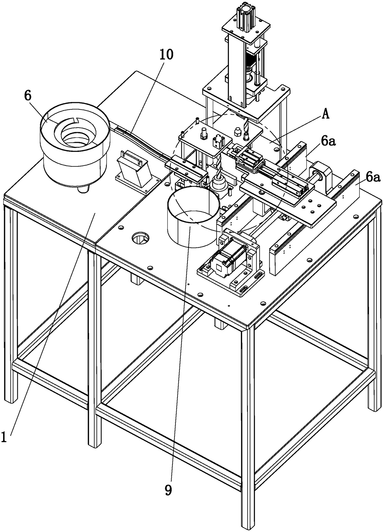
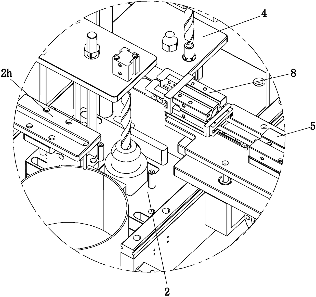
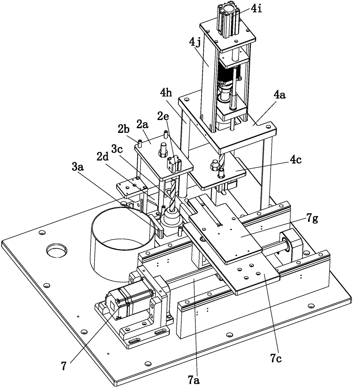
[0021] refer to Figure 1 to Figure 7The shown multi-station automatic chamfering machine includes a working platform 1, an upper processing part 2, a lower processing part 4 and feeding parts for feeding the upper processing part 2 and the lower processing part 4, and the working platform 1 The working plane of the working platform is a rectangular structure. One end in the width direction of the top of the working platform 1 is provided with a vibrating plate 6, and the other end is provided with two symmetrical feeding guide plates 6a. The feeding parts include a feeding cylinder 5, which can slide horizontally. Between the two feeding guide plates 6a, a lifting cylinder 5a is also provided below the feeding cylinder 5, the upper processing part 2 is arranged above the center of the working platform 1, and the lo...


PUM


Abstract

The invention relates to the technical field of inner corner chamfering, in particular to a multi-station automatic inner corner chamfering machine. The multi-station automatic inner corner chamferingmachine comprises a working platform, an upper machining portion, a lower machining portion and a feeding component. The working plane of the working platform is of a rectangular structure. A vibration disc is arranged at one end of the top of the working platform, and two symmetric feeding guide plates are arranged at the other end of the top of the working platform. The feeding component comprises a feeding air cylinder. The feeding air cylinder is arranged between the two feeding guide plates in a manner of being capable of horizontally sliding. A lifting air cylinder is further arranged below the feeding air cylinder. The upper machining portion is arranged above the center of the working platform. The lower machining portion is arranged below the side of the upper machining portion.The upper machining portion and the lower machining portion are located between the feeding air cylinder and the vibration disc. A first inner corner chamfering part used for cooperating with the lower machining portion for inner corner chamfering is arranged above the working platform. A second inner corner chamfering part used for cooperating with the upper machining portion for inner corner chamfering is arranged at the bottom of the working platform. The multi-station automatic inner corner chamfering machine has the advantages of being simple in structure and low in maintenance cost, androtary workpieces can be effectively subjected to inner corner chamfering.

Description

technical field [0001] The invention relates to the technical field of chamfering inner corners, in particular to a multi-station automatic chamfering inner corner machine. Background technique [0002] With the continuous development of modern manufacturing and processing technology, the application of rotary workpieces is becoming more and more extensive, such as shaft parts, discs and other parts. Taking shaft parts as an example, some traditional shaft rotary parts are used before they are used. According to the actual use requirements, the outer wall of the end will be chamfered. There are also some special working environments and work needs, which makes the inner wall of these shaft rotary parts also need to be chamfered. Some traditional The chamfering machine only has the ability to chamfer the outer end of the workpiece, and cannot chamfer the inner wall of the workpiece well, but there are also some large manufacturers that have equipment that can chamfer the inne...

Claims


Application Information

Patent Timeline
IPC IPC(8): B23D79/04B23Q7/00B23Q7/10B23Q7/08B23Q7/14
CPCB23D79/04B23Q7/00B23Q7/08B23Q7/10B23Q7/1494
Inventor 黄健森
Owner 黄健森
Why Eureka
Try Eureka