
Automatic embedment injection molding production line for bearing roller

A production line and bearing technology, which is applied in the field of automatic bearing roller embedded injection molding production line, can solve the problems such as long operation time of manually inserting bearings and removing bearing rollers, unfavorable automatic and mechanized production of bearing rollers, affecting product quality stability and production efficiency, etc. Achieve the effect of improving quality stability and product qualification rate, realizing production automation, and leveling the cutting surface

Pending Publication Date: 2018-07-20
NINGBO HAIMAIKE AUTOMATION TECH CO LTD
View PDF0 Cites 1 Cited by
  • Summary
  • Abstract
  • Description
  • Claims
  • Application Information

AI Technical Summary

Problems solved by technology

[0003] However, the above-mentioned production method has the following defects: (1) After the injection molding machine is opened, the operation time of manually inserting the bearing and removing the bearing roller is long and unstable, which affects the quality stability of the final product; (2) When manually removing the nozzle Due to the deviation of human vision, the shearing surface is uneven, which can easily lead to unqualified products, and if one operation is unsuccessful, repeated operations will be required, which will seriously affect the quality stability of the product and the improvement of production efficiency; (3) due to the After the injection molding of the roller is completed, the temperature is high, so gloves must be worn when taking it out manually. The oil stains on the gloves will contaminate the surface of the bearing roller, resulting in a decrease in the quality of the bearing roller; (4) When manually inserting the bearing into the injection molding, there are hidden dangers to personal safety In summer production, the high temperature near the injection molding machine will affect the physical and mental health of the operator, and the labor cost is high, which is not conducive to the automation and mechanization of bearing rollers.

Method used


Image

  • Automatic embedment injection molding production line for bearing roller
  • Automatic embedment injection molding production line for bearing roller
  • Automatic embedment injection molding production line for bearing roller

Examples


Embodiment 1

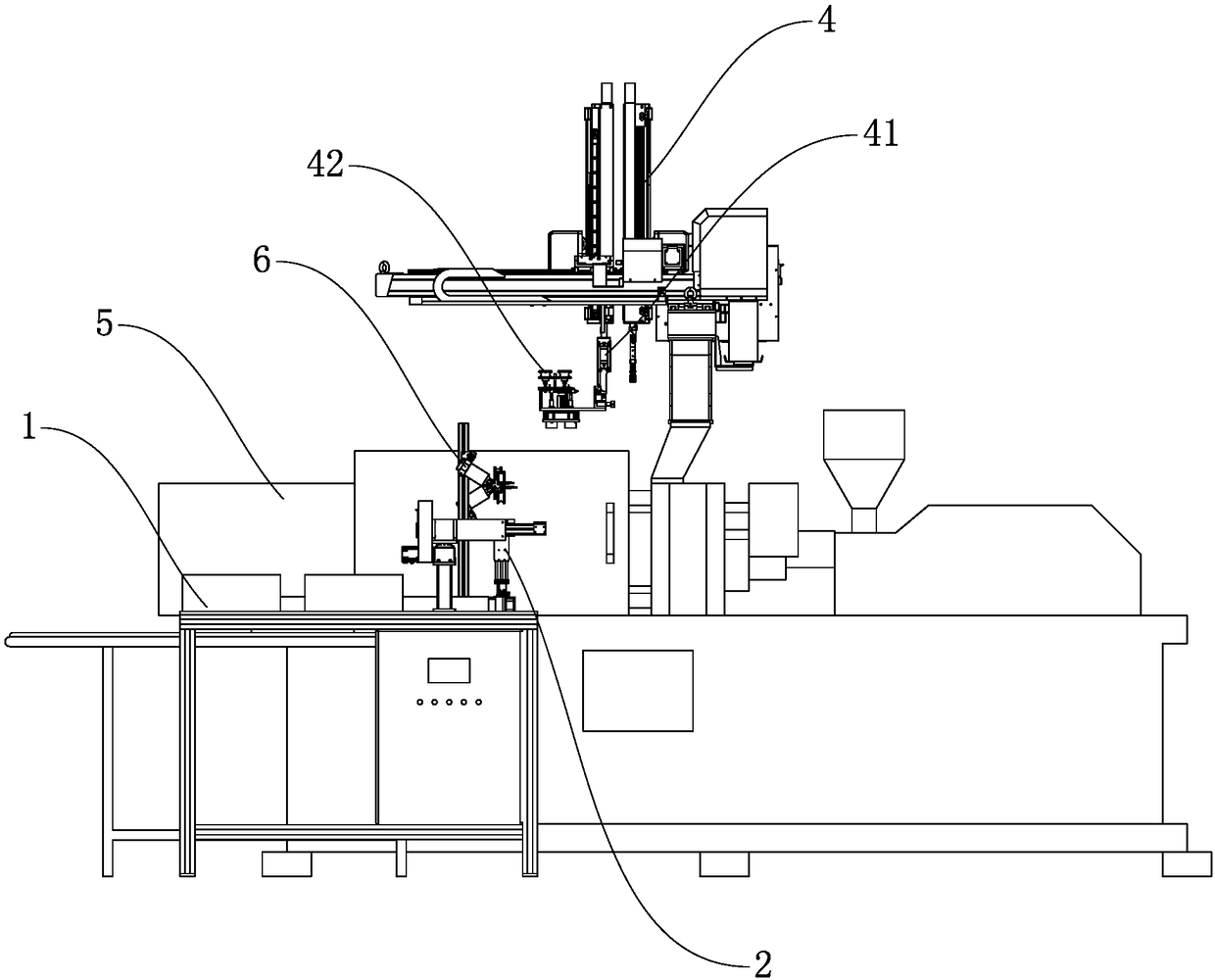
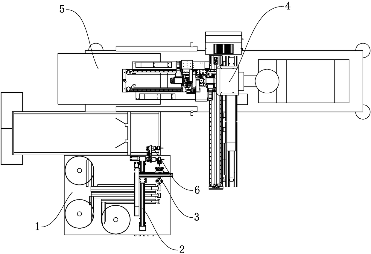
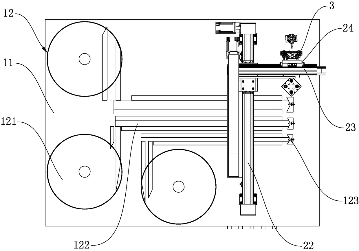
[0034] Embodiment 1: As shown in the figure, a bearing roller is automatically embedded in an injection molding production line, including: a bearing feeding device 1 , a bearing grabbing device 2 , a bearing positioning device 3 , a manipulator 4 , an injection molding machine 5 and a nozzle shearing device 6 . The bearing feeding device 1 provides the bearings 7 arranged automatically and orderly, the bearing grabbing device 2 takes out the arranged bearings 7 from the bearing feeding device 1 and transfers them to the bearing positioning device 3 for positioning, and the manipulator 4 positions the bearings from the bearing Take out the positioned bearing 7 from the device 3, transfer it and insert it into the mold of the injection molding machine 5 for injection molding, and the manipulator 4 takes out the injected bearing roller 8 output from the demoulding side of the injection molding machine 5, and transfers it to the nozzle for shearing Device 6, the nozzle shearing de...

Embodiment 2

[0035] Embodiment 2: As shown in the figure, a bearing roller is automatically embedded in an injection molding production line, including: a bearing feeding device 1 , a bearing grabbing device 2 , a bearing positioning device 3 , a manipulator 4 , an injection molding machine 5 and a nozzle shearing device 6 . The bearing feeding device 1 provides the bearings 7 arranged automatically and orderly, the bearing grabbing device 2 takes out the arranged bearings 7 from the bearing feeding device 1 and transfers them to the bearing positioning device 3 for positioning, and the manipulator 4 positions the bearings from the bearing Take out the positioned bearing 7 from the device 3, transfer it and insert it into the mold of the injection molding machine 5 for injection molding, and the manipulator 4 takes out the injected bearing roller 8 output from the demoulding side of the injection molding machine 5, and transfers it to the nozzle for shearing Device 6, the nozzle shearing de...

Embodiment 3

[0046] Embodiment 3: As shown in the figure, a bearing roller is automatically embedded in an injection molding production line. The difference from Embodiment 2 is that the bearing positioning device 3 includes a positioning block assembly 31 fixed above the feeding platform 11, and the positioning block assembly 31 includes A positioning block 311 and four positioning pins 312 . The positioning block 311 is fixed above the feeding platform 11 , and the positioning pins 312 are arranged vertically and symmetrically on the positioning block 311 for positioning the inner rings of the four bearings 7 respectively. The position of the positioned bearing 7 on the positioning block 311 , the position of the bearing 7 absorbed on the manipulator 4 and the position of the bearing 7 embedded in the injection mold all correspond to each other.

[0047] In this embodiment, the positioning block assembly 31 also includes a buffer mechanism, which is a spring (not shown) arranged between ...


PUM


Abstract

The invention discloses an automatic embedment injection molding production line for a bearing roller. The automatic embedment injection molding production line for the bearing roller is characterizedby comprising a bearing supply device, a bearing gripping device, a bearing locating device, a mechanical arm, an injection molding machine and a nozzle shearing device, wherein the bearing supply device supplies bearings which are automatically arranged in order, the bearing gripping device takes the arranged bearing from the bearing supply device and transfers the bearing to the bearing locating device for locating, the mechanical arm takes out the located bearing from the bearing locating device, transfers the bearing and embeds the bearing into a mold of the injection molding machine forinjection molding, the mechanical arm takes out the injection molded bearing roller which is output from the demolding side of the injection molding machine and transfers the bearing roller to the nozzle shearing device, after the nozzle shearing device shears the nozzle of the bearing roller, the bearing roller product is obtained, and the mechanical arm transfers the bearing roller product to the outlet end of the production line. The automatic embedment injection molding production line for the bearing roller has the advantages of achieving mechanical and automatic production, guaranteeingthe cut surface quality of the nozzle of the bearing roller, improving the product quality stability and production efficiency and relieving the labor intensity of workers.

Description

technical field [0001] The invention relates to the field of automation equipment, in particular to a bearing roller automatic embedded injection molding production line. Background technique [0002] The insert of the bearing roller (also known as the plastic roller) is a bearing. The bearing roller is a traditional mechanical accessory, which is widely used in the engineering field and daily life, and has a huge demand. At present, in the production process of the bearing roller, the bearing is usually manually embedded into the injection mold, and the bearing roller is manually taken out after the injection molding is completed, and the nozzle material between the products is manually removed. [0003] However, the above-mentioned production method has the following defects: (1) After the injection molding machine is opened, the operation time of manually inserting the bearing and removing the bearing roller is long and unstable, which affects the quality stability of the...

Claims


Application Information

Patent Timeline
IPC IPC(8): B29C45/14B29C45/42B29C45/38B29L31/04
CPCB29C45/14008B29C45/382B29C45/4225B29L2031/04
Inventor 韩立勇刘传凯葛冠超王峰
Owner NINGBO HAIMAIKE AUTOMATION TECH CO LTD
Learn More