
Dye vat for textile processing

A textile and rotating shaft technology, applied in the field of textile processing, can solve the problems of inconvenient dye color comparison, inability to ensure color matching, affecting the dyeing effect, etc., to achieve the effect of increasing printing and dyeing efficiency, simple structure, and easy operation by workers

Inactive Publication Date: 2018-07-20
海宁德里法新材料有限公司
View PDF4 Cites 2 Cited by
  • Summary
  • Abstract
  • Description
  • Claims
  • Application Information

AI Technical Summary

Problems solved by technology

When the existing dye tank dyes the fabric, it is inconvenient to compare the color of the dye in the dye tank, and cannot ensure that the color of the fabric after dyeing is consistent. At the same time, the guide rollers in the dye tank are all fixed devices. Insufficient tension will cause folding, which will affect the dyeing effect, making reprocessing more troublesome and affecting work efficiency

Method used


Image

  • Dye vat for textile processing
  • Dye vat for textile processing
  • Dye vat for textile processing

Examples


Embodiment Construction

[0019] The following will clearly and completely describe the technical solutions in the embodiments of the present invention with reference to the accompanying drawings in the embodiments of the present invention. Obviously, the described embodiments are only some, not all, embodiments of the present invention.

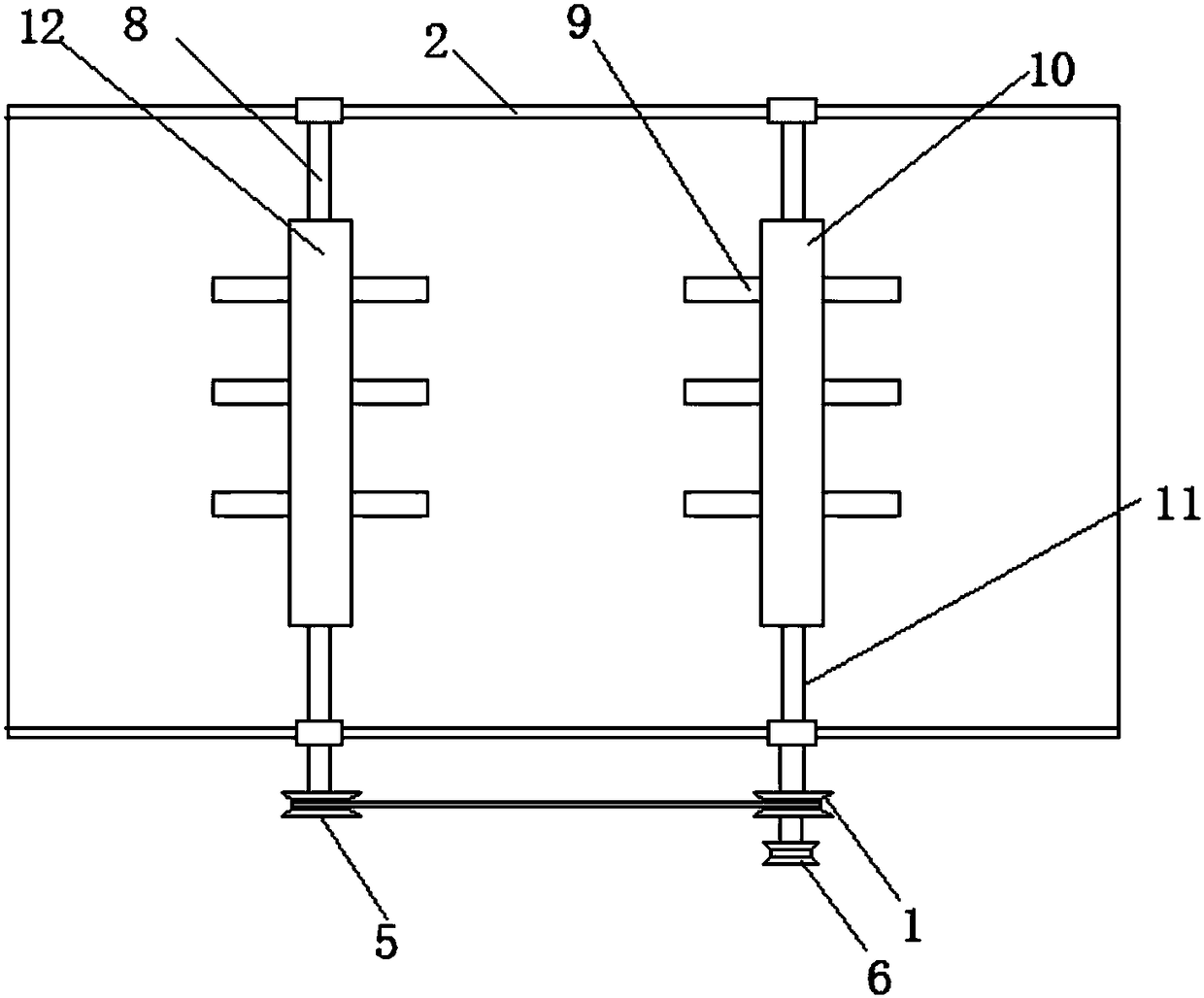
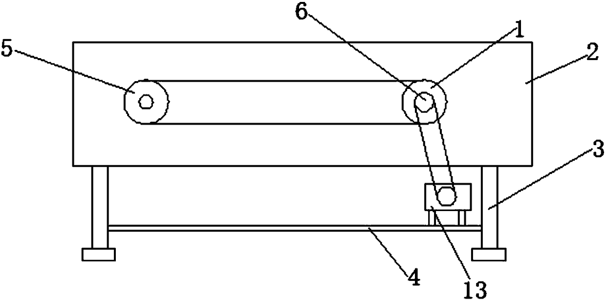
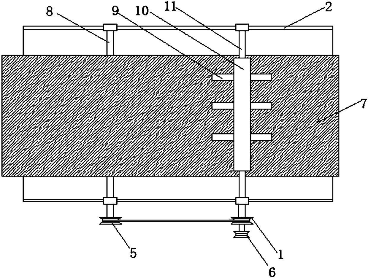
[0020] refer to Figure 1-3 , a kind of dyeing tank for textile processing, including printing and dyeing tank 2, the two side walls of the printing and dyeing tank 2 are provided with round holes for supplying and installing bearing seats, bearing seats are installed in the round holes, and two bearing seats are respectively fixed There are a first rotating shaft 8 and a second rotating shaft 11, wherein a first roller 12 is installed on the first rotating shaft 8, a second roller 10 is installed on the second rotating shaft 11, and the first roller 12 and the second All be welded with column 9 on the outer side wall of two rollers 10, the first pulley 5 and the sec...


PUM


Abstract

The invention discloses a dye vat for textile processing. The dye vat for textile processing includes a printing and dyeing vat; round holes for mounting bearing seats are formed in the two side wallsof the printing and dyeing vat, the bearing seats are installed in the round holes, and a first rotation shaft and a second rotation shaft are fixed to the bearing seats respectively, wherein a firstroller wheel is mounted on the first rotation shaft, a second roller wheel is mounted on the second rotation shaft, upright columns are welded to the outer side wall of the first roller wheel and theouter side wall of the second roller wheel, and a first belt wheel and a second belt wheel are mounted at the ends, outside the printing and dyeing vat, of the first and second rotation shafts respectively. The dye vat for textile processing is simple in structure, low in production cost and is extremely convenient to produce and maintain; the upright columns are arranged on the dye vat and can drag textiles to rotate in the dye vat, and therefore the textiles can be further fully printed and dyed and cannot tie; by the adoption of a rotation printing and dyeing mode, the printing and dyeingefficiency can be greatly improved, and the dye vat for textile processing is extremely easy to operate manually.

Description

technical field [0001] The invention relates to the technical field of textile processing, in particular to a dye tank for textile processing. Background technique [0002] Dyeing tank, a kind of printing and dyeing machine, specifically a dyeing machine with an inclined dyeing tank. There are two curved segments joined by a straight segment placed at an angle. [0003] The dye tank is a device used to dye fabrics. When the commonly used square dye tank dyes the fabric, the fabric is in a loose open width state, so it is not easy to scratch the fabric, and the dyeing liquid has good permeability, which can make the fabric The dyed fabric has a soft luster and a soft, full-bodied feel. When the existing dye tank dyes the fabric, it is inconvenient to compare the color of the dye in the dye tank, and cannot ensure that the color of the fabric after dyeing is consistent. At the same time, the guide rollers in the dye tank are all fixed devices. Insufficient tension will caus...

Claims


Application Information

Patent Timeline
Patent Type & Authority Applications(China)
IPC IPC(8): D06B3/20D06B23/14
CPCD06B3/206D06B23/14
Inventor 钱智勇
Owner 海宁德里法新材料有限公司
Learn More