
Laboratory multi-section ventilation energy-saving control system

An energy-saving control system and control system technology, applied in the direction of heating and ventilation control system, heating and ventilation safety system, space heating and ventilation control input, etc., can solve problems such as unfavorable energy saving and lack of air volume control function

Pending Publication Date: 2018-07-20
苏州明良智能科技有限公司
View PDF0 Cites 6 Cited by
  • Summary
  • Abstract
  • Description
  • Claims
  • Application Information

AI Technical Summary

Problems solved by technology

[0002] The ventilation of the laboratory plays a vital role in the environmental quality of the laboratory and the health of laboratory operators. In order to prevent the pollutants produced in the experiment from spreading into the laboratory, all kinds of laboratories are equipped with ventilation systems, but The existing ventilation system either does not have the function of air volume control, as long as one fume hood in the system is turned on and used, the exhaust motor will run at full capacity, which is not conducive to energy saving

Method used


Image

  • Laboratory multi-section ventilation energy-saving control system
  • Laboratory multi-section ventilation energy-saving control system
  • Laboratory multi-section ventilation energy-saving control system

Examples


Embodiment Construction

[0037] The present invention will be further described in detail below through specific embodiments in conjunction with the accompanying drawings.

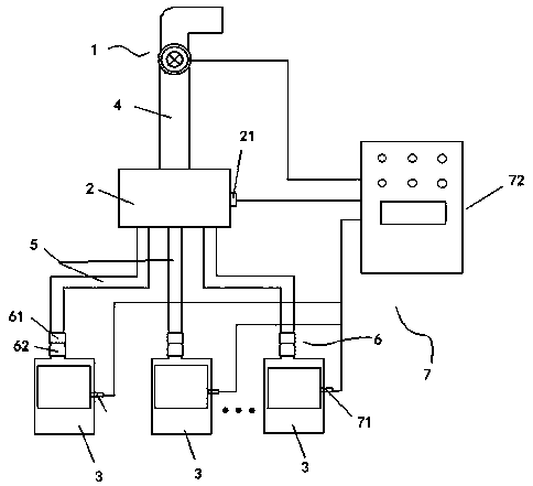
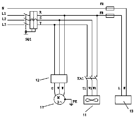
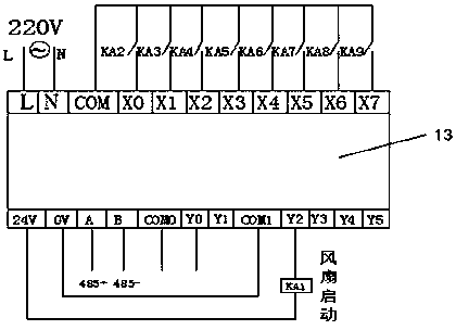
[0038] Such as figure 1 As shown, a laboratory multi-stage ventilation energy-saving control system includes a frequency conversion fan 1, a centralized box 2 and a plurality of fume hoods 3 connected to the centralized box 2, and the connecting gas path from the variable frequency fan 1 to the centralized box 2 is Ventilation main pipe 4, the connecting gas path from the concentration box 2 to the fume hood 3 is a ventilation branch pipe 5, the ventilation branch 5 is provided with a damper 6, and the fume hood 3 is connected with a surface wind speed monitoring and control system 7, The surface wind speed monitoring and control system 7 includes a surface wind speed sensor 71 installed in each fume hood 3 and a variable air volume controller 72 electrically connected to the surface wind speed sensor 71, and the variable air volu...


PUM


Abstract

The invention discloses a laboratory multi-section ventilation energy-saving control system, and relates to the technical field of laboratory ventilation equipment. The laboratory multi-section ventilation energy-saving control system comprises a frequency conversion draught fan, a centralizing box and a plurality of ventilation cabinets connected with the centralizing box. Air valves are arrangedon ventilation branches from the centralizing box to the ventilation cabinets. The ventilation cabinets are connected with a face air speed monitoring and control system. The face air speed monitoring and control system comprises face air speed sensors arranged in the ventilation cabinets and a variable air volume controller. The variable air volume controller is connected with the frequency conversion draught fan and measures the aperture of the ventilation cabinets in real time. Meanwhile, the face air speed sensors measure the face air speed in real time and convert the face air speed intovoltage signals transmitted to the variable air volume controller. The variable air volume controller compares the face air speed actual value and the set value, if the face air speed is not in the set value range, the variable air volume controller outputs control signals to the frequency conversion draught fan, and the frequency conversion draught fan receives the control signals and adjusts the ventilation air volume. The laboratory multi-section ventilation energy-saving control system capable of conducting intelligent frequency conversion according to the actual air utilization volume and achieving energy saving is provided.

Description

technical field [0001] The invention relates to the technical field of laboratory ventilation equipment, in particular to a laboratory multi-stage ventilation energy-saving control system. Background technique [0002] The ventilation of the laboratory plays a vital role in the environmental quality of the laboratory and the health of laboratory operators. In order to prevent the pollutants produced in the experiment from spreading into the laboratory, all kinds of laboratories are equipped with ventilation systems, but The existing ventilation system either does not have the function of air volume control. As long as one fume hood in the system is turned on and used, the exhaust motor will run at full capacity, which is not conducive to energy saving. Contents of the invention [0003] This application provides a multi-stage ventilation energy-saving control system for laboratories that realizes energy saving by intelligent frequency conversion air supply according to the...

Claims


Application Information

Patent Timeline
IPC IPC(8): F24F11/65F24F11/32F24F11/77F24F110/10F24F110/20F24F110/30
CPCY02B30/70
Inventor 徐明利吴博
Owner 苏州明良智能科技有限公司
Learn More