Failure detecting method for relay in inverter

A detection method and relay technology, applied in the direction of circuit breaker testing, etc., can solve the problems of false alarm relay abnormality, wrong wiring, etc., and achieve the effect of avoiding misjudgment

Inactive Publication Date: 2018-07-20
JIANGSU EVER SOLAR NEW ENERGY CO LTD
View PDF5 Cites 2 Cited by
  • Summary
  • Abstract
  • Description
  • Claims
  • Application Information

AI Technical Summary

Problems solved by technology

For example, wrong wiring, while the relay is normal, it will also falsely report that the relay is abnormal
Or due to the abnorma

Method used


Image

  • Failure detecting method for relay in inverter
  • Failure detecting method for relay in inverter

Examples


Example Embodiment

[0037] The preferred embodiments of the present invention will be described in detail below with reference to the accompanying drawings, so that the advantages and features of the present invention can be more easily understood by those skilled in the art. It should be noted here that the description of these embodiments is used to help understand the present invention, but does not constitute a limitation to the present invention. In addition, the technical features involved in the various embodiments of the present invention described below can be combined with each other as long as they do not conflict with each other.

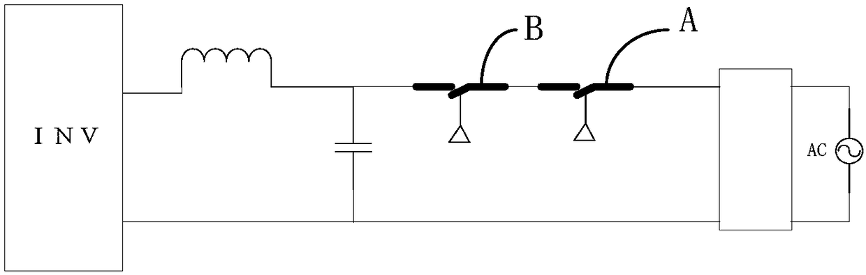
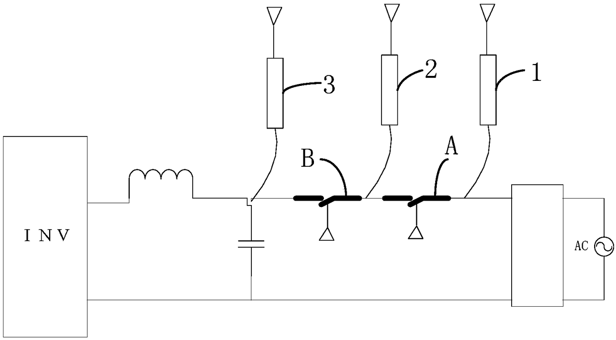
[0038] This embodiment provides a method for detecting failure of a relay in an inverter. The circuit diagram of the inverter is as follows figure 1 As shown, it includes an inverter module, an inductor, a capacitor, a control circuit (not shown in the figure), and multiple relays, which are connected in series from the grid side or the load side in sequence, ...


PUM


Abstract

The invention discloses a failure detecting method for a relay in an inverter. The method comprises the following steps: step A, one is selected successively as a tested relay among all other relays except a Nth relay at a longest distance to a grid side or load side and thus the relay between the tested relay and the grid side or load side is turned off and the relay between the tested relay andthe inverter of the grid side or load side is turned off; step B, whether the tested relay fails to work is determined according to voltages at the two sides or one side of the tested relay in on andoff states; step C0, an inverter control circuit generates a detection voltage; and step C, all other relays are disconnected and whether the Nth relay fails to work is determined based on voltages atthe two sides or one side of the Nth relay in on and off states; and the steps A and B are performed by (N-1) times to determine whether all other relays except the Nth relay at a longest distance tothe grid side or load side fails to work. With the method disclosed by the invention, a false determination situation can be avoided and detection blind point existence is avoided.

Description

technical field [0001] The invention relates to the field of inverter detection, in particular to a failure detection method for a relay in an inverter. Background technique [0002] Due to safety requirements in conventional inverters, two or more relays need to be connected in series near the grid side or load side to achieve redundant protection, such as figure 1 shown. Before two or more relays are closed, it is first necessary to judge whether the functions of each relay are good so as to realize the action of closing and opening. After the relay function determines that the relay has no abnormal aging conditions, it can continue to connect to the grid or output power. [0003] For detecting whether the function of the relay is good or not, there are currently existing detection circuits, but there are detection blind spots or misjudgments. For example, wrong wiring, while the relay is normal, it will also falsely report that the relay is abnormal. Or due to the con...

Claims


Application Information

Patent Timeline
IPC IPC(8): G01R31/327
CPCG01R31/327
Inventor 叶海军卢盈廖小俊
Owner JIANGSU EVER SOLAR NEW ENERGY CO LTD
Why Eureka
Try Eureka