
Server-power-on-state monitoring system and method and computer storage and equipment

A monitoring system and server technology, applied in the computer field, can solve the problems of difficult positioning, high cost of analysis and positioning, and low probability of occurrence.

Inactive Publication Date: 2018-07-20
ZHENGZHOU YUNHAI INFORMATION TECH CO LTD
View PDF4 Cites 21 Cited by
  • Summary
  • Abstract
  • Description
  • Claims
  • Application Information

AI Technical Summary

Problems solved by technology

The power-on abnormality before BIOS (Basic Input Output System, Basic Input Output System) startup is an extremely difficult problem in the field of storage systems. The probability of its occurrence is relatively small, but the analysis and location are very costly and difficult, such as component damage , Power supply overvoltage, undervoltage, etc. can cause it. It would be very time-consuming and laborious to measure signals only by hardware engineers. CPLD (Complex Programmable Logic Device, complex programmable logic device), as a key component of power-on sequence control, accurately defines The sequence of each key voltage signal, if a certain voltage signal fails to start, the electrical signals after this voltage signal will also fail to start, so the storage system cannot start

Method used


Image

  • Server-power-on-state monitoring system and method and computer storage and equipment
  • Server-power-on-state monitoring system and method and computer storage and equipment
  • Server-power-on-state monitoring system and method and computer storage and equipment

Examples


Embodiment Construction

[0038] The following will clearly and completely describe the technical solutions in the embodiments of the present invention with reference to the accompanying drawings in the embodiments of the present invention. Obviously, the described embodiments are only some, not all, embodiments of the present invention. Based on the embodiments of the present invention, all other embodiments obtained by persons of ordinary skill in the art without making creative efforts belong to the protection scope of the present invention.

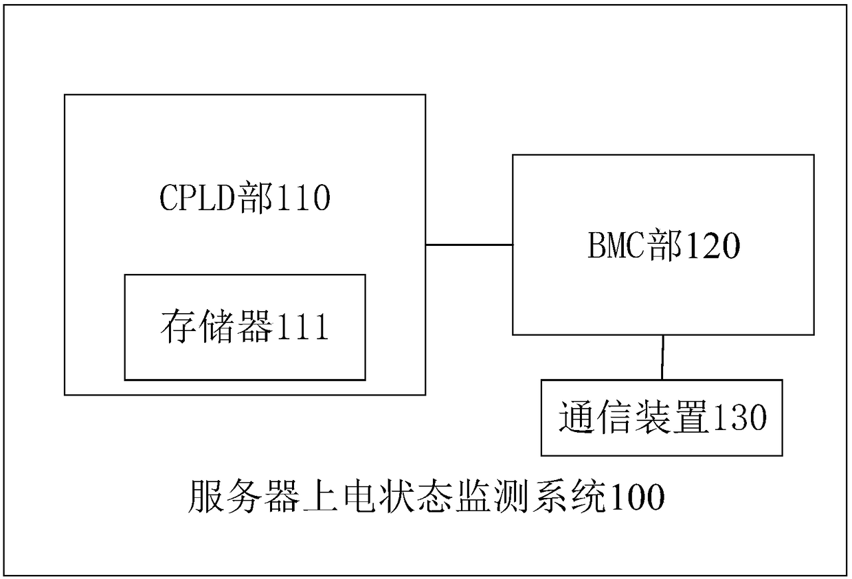
[0039] Please refer to figure 1 , figure 1 A schematic composition diagram of a server power-on status monitoring system provided for a specific embodiment of the present invention.

[0040] In a specific implementation manner of the present invention, the embodiment of the present invention provides a server power-on state monitoring system 100, including: CPLD part 110, BMC part 120, communication device 130;

[0041] The CPLD part 110 is used to control t...


PUM


Abstract

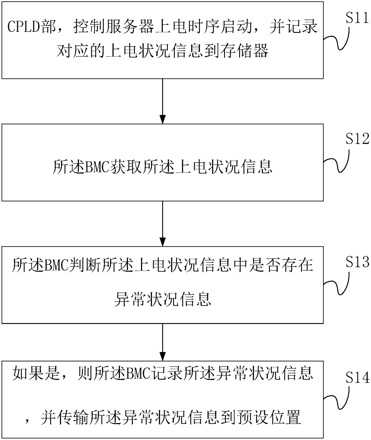
The invention provides a server-power-on-state monitoring system and method and a computer storage and equipment. The server-power-on-state monitoring system comprises a CPLD part, a BMC part and a communication device, wherein the CPLD part is used for controlling server power-on-time-sequence starting and recording corresponding power-on-condition information to the storage; the BMC is used forobtaining the power-on-condition information and judging whether abnormal condition information exists in the power-on-condition information or not, and if the abnormal condition information exists inthe power-on-condition information, the abnormal condition information is recorded; the communication device is used for transmitting the abnormal condition information to a preset position. According to the server-power-on-state monitoring system, when the CPLD part controls a server to be powered on, the power-on-condition information recorded by the CPLD part in the storage can be monitored, whether the abnormal condition information exists in the power-on-condition information or not is judged, and the abnormal condition information is recorded and transferred to the preset position accordingly so that the record can be conveniently used at a later time; the server power-on working state is analyzed, and the server power-on abnormal condition can be simply and accurately detected at alow cost.

Description

technical field [0001] The invention relates to the field of computer technology, in particular to a server power-on state monitoring system and method, computer memory and equipment. Background technique [0002] As a kind of computer equipment, the server is a kind of computer equipment. When starting up, the power-on sequence of each component of the computer is the power supply on the main board. From the initial voltage input of the voltage adapter to the final generation of CPU power supply, there are strict start-up sequence controls. The power-on abnormality before BIOS (Basic Input Output System, Basic Input Output System) startup is extremely difficult to locate in the field of storage systems. The probability of its occurrence is relatively small, but the analysis and location are very costly and difficult, such as component damage , Power supply overvoltage, undervoltage, etc. can cause it. It would be very time-consuming and laborious to measure signals only by ...

Claims


Application Information

Patent Timeline
IPC IPC(8): G06F11/30
CPCG06F11/3058G06F11/3003
Inventor 班华堂王兴隆乔英良刘宝阳慈潭龙田玉鹏宿燕鸣
Owner ZHENGZHOU YUNHAI INFORMATION TECH CO LTD
Learn More