
Method for constructing fracture recognition model and application

A technology for identifying models and building methods, applied in the field of medical imaging, which can solve the problems of dependence on the accuracy and efficiency of identification, and high requirements for doctors, so as to reduce the diagnosis time and reduce the misdiagnosis rate.

Active Publication Date: 2018-07-20
HUIYING MEDICAL TECH (BEIJING) CO LTD
View PDF5 Cites 51 Cited by
  • Summary
  • Abstract
  • Description
  • Claims
  • Application Information

AI Technical Summary

Problems solved by technology

It can be seen that the above recognition requires a high level of doctors, and the accuracy and efficiency of recognition depend on the experience level of doctors.

Method used


Image

  • Method for constructing fracture recognition model and application
  • Method for constructing fracture recognition model and application
  • Method for constructing fracture recognition model and application

Examples


Embodiment 1

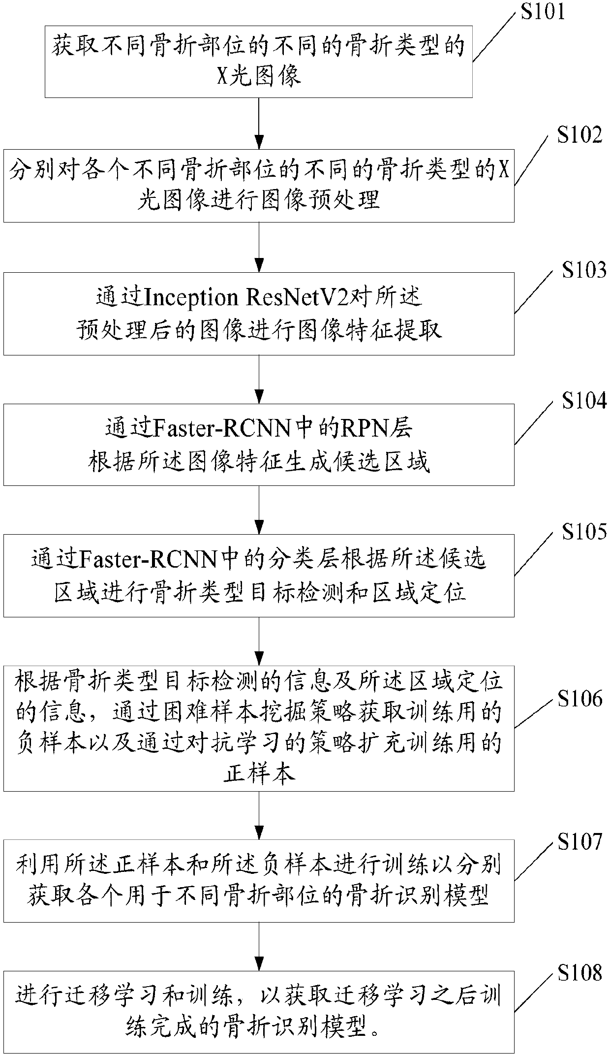
[0080] Such as figure 1 As shown, S101, obtain X-ray images of different fracture types at different fracture sites.

[0081] Specifically, since fractures of different fracture types at different locations have different characteristics, in order to better construct a fracture identification model, it is preferred to obtain X-ray images of different fracture types at different fracture locations. Among them, the images of different fracture parts are marked according to the fracture types, so as to obtain the fracture types containing different fracture parts and their corresponding position information (that is, the doctor's marked area described later); wherein, the different fracture parts include: hand , foot, upper limbs, lower limbs, chest, spine, head, etc.; different types of fractures include: open fractures, complete fractures, fractures, greenstick fractures, dislocations, irregular edges, etc. From the perspective of probability, the transformation of samples can...

Embodiment 2

[0134] Such as Figure 4 As shown, the present application also provides a fracture recognition method based on the aforementioned fracture recognition model, comprising the following steps:

[0135] S401, inputting the X-ray image of the injured part of the patient to be identified;

[0136] S402, performing image preprocessing on the X-ray image;

[0137] S403, performing image feature extraction on the preprocessed image;

[0138] S404, using the trained fracture identification model corresponding to the injured part of the patient to identify the type of fracture and detect the fracture area.

[0139] From the above, the above-mentioned steps help to accurately predict the fracture type and regional location, greatly reduce the doctor's diagnosis time, and reduce the rate of misdiagnosis.

[0140] Wherein, after said S404, it also includes:

[0141] S405, use the non-maximum value suppression method to process the candidate frames obtained through the fracture recognit...


PUM


Abstract

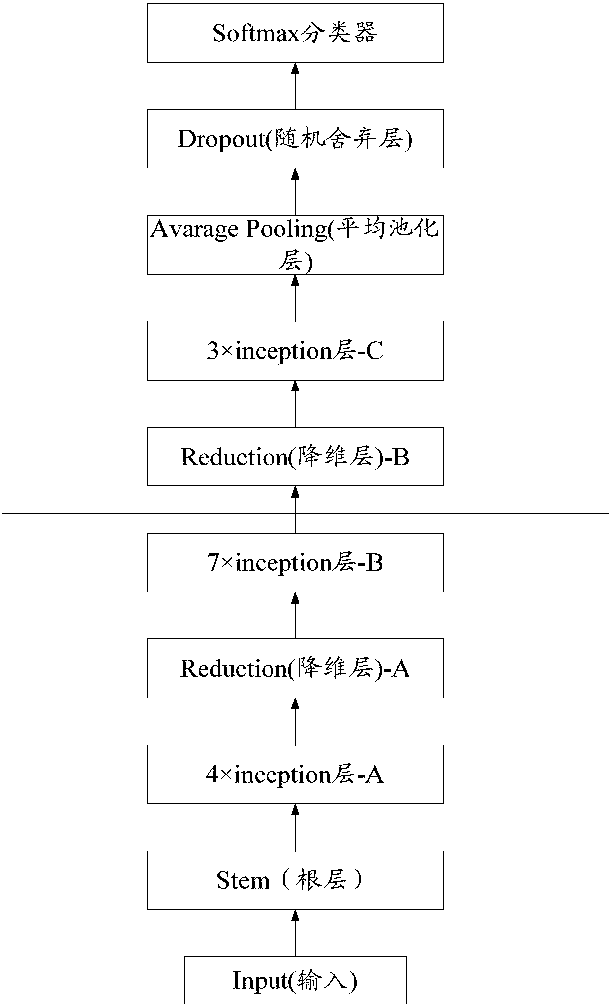
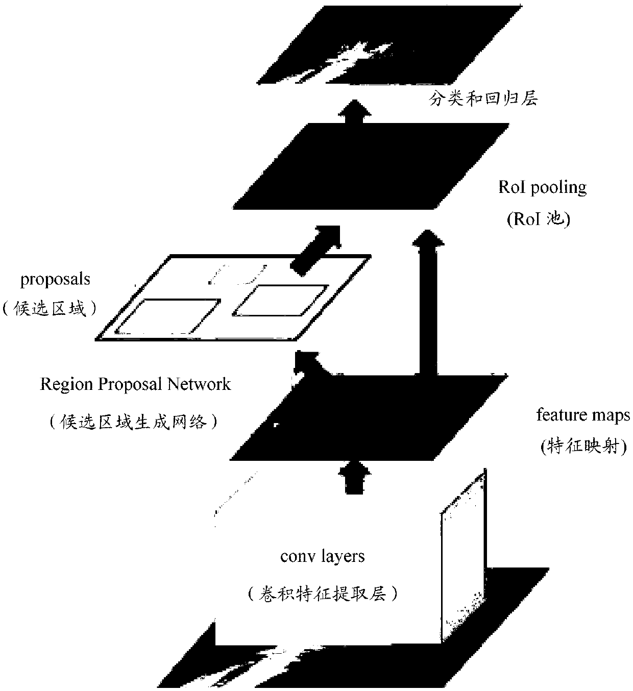
The invention provides a method for constructing a fracture recognition model and application. The method comprises: step A, acquiring X-ray images of different fracture types of different fracture parts; step B, carrying out image preprocessing on the X-ray images of different fracture types of different fracture parts; step C, carrying out image feature extraction on the preprocessed images; step D, generating a candidate region according to the image features; step F, carrying out fracture type target detection and region localization on the candidate region; step G, according to a facturetype target detection score, carrying out difficult sample mining to obtain negative samples for training; step K, expanding positive samples for training based on an adversarial learning strategy; and step H, training is carried out by using the positive samples and the negative samples so as to obtain all fracture recognition models for different fracture parts. Therefore, the fracture type andthe regional position can be predicted accurately by using the model, so that the diagnosis time of the doctor is reduced substantially and the missed diagnosis and misdiagnosis rates are reduced.

Description

technical field [0001] The invention relates to the field of medical imaging, in particular to a construction method and application of a fracture recognition model. Background technique [0002] Fracture is a common disease in daily life. When diagnosing a patient's fracture, the doctor usually takes X-rays of the patient's fracture site, and according to the X-ray image of the fracture site, the location and type of the fracture are determined according to the doctor's experience. Perform visual identification. It can be seen that the above-mentioned recognition requires a high level of doctors, and the accuracy and efficiency of recognition depend on the experience level of doctors. Therefore, there is an urgent need for a fracture recognition model. It is beneficial to accurately and quickly realize the identification of the fracture type and the location of the fracture area, thereby providing a reference for the doctor's diagnosis, greatly reducing the doctor's diagn...

Claims


Application Information

Patent Timeline
IPC IPC(8): G06T7/00
CPCG06T7/0012G06T2207/10116G06T2207/20081G06T2207/20084G06T2207/30008
Inventor 柴象飞郭娜顾一驰陈聪
Owner HUIYING MEDICAL TECH (BEIJING) CO LTD
Learn More