Applicable Power Flow Calculation Method in Rotor Angle Control Mode

A technology of power flow calculation and control mode, which is applied in the field of power flow calculation and can solve the problems that the power flow algorithm is no longer applicable

Active Publication Date: 2021-05-04
STATE GRID HENAN ELECTRIC POWER ELECTRIC POWER SCI RES INST +2
View PDF6 Cites 0 Cited by
  • Summary
  • Abstract
  • Description
  • Claims
  • Application Information

AI Technical Summary

Problems solved by technology

Due to different active power tracking mechanisms, traditional power flow algorithms are no longer applicable

Method used


Image

  • Applicable Power Flow Calculation Method in Rotor Angle Control Mode
  • Applicable Power Flow Calculation Method in Rotor Angle Control Mode
  • Applicable Power Flow Calculation Method in Rotor Angle Control Mode

Examples


Embodiment Construction

[0030] The following will clearly and completely describe the technical solutions in the embodiments of the present invention with reference to the accompanying drawings in the embodiments of the present invention. Obviously, the described embodiments are only some, not all, embodiments of the present invention. Based on the embodiments of the present invention, all other embodiments obtained by persons of ordinary skill in the art without making creative efforts belong to the protection scope of the present invention.

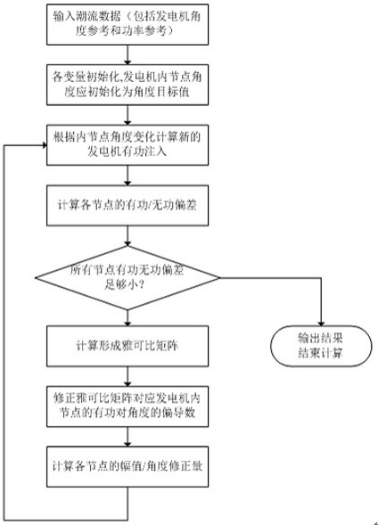
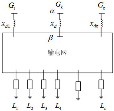
[0031] Firstly, the new algorithm uses the power grid model with the addition of generator internal nodes, and then expounds the equations of the corresponding internal nodes and the influence of rotor angle control on the output of the generator. Then analyze the influence of these factors on the power flow calculation. Finally, the detailed steps of power flow calculation are given, that is, the specific steps of the power flow calculation method are given i...


PUM


Abstract

The invention discloses a power flow calculation method available after applying rotor angle control (RAD control) to a power grid. The calculation steps are as follows: First, while inputting the known data of the traditional power flow, input the internal node angle reference and active power reference of the generator. The variables are then initialized and the generator internal node angles are set as angle references. Then iterative calculation is started to calculate the active and reactive deviations of each node, and the active power injection of the nodes in the RAD generator should be added with the correction amount obtained according to the angle deviation. Then calculate the Jacobian matrix, in which the partial derivative of the active power of the RAD generator to the angle is compared with the traditional power flow, and the proportional gain of the rotor angle controller needs to be multiplied by the rated capacity of the generator. Then use Newton's method to obtain the voltage / amplitude correction value of each node and the new node voltage / amplitude to complete an iteration. The aforementioned iterations are repeated until the active / reactive power deviation of each node is less than the preset threshold, and the power flow calculation can be completed.

Description

technical field [0001] The invention relates to the field of power system analysis and control, in particular to a power flow calculation method applicable in a rotor angle control mode. Background technique [0002] The power system has been using a combination of decentralized primary frequency regulation and centralized automatic generation control (AGC, including secondary frequency recovery and tie-line control, etc.) to control the active power of generation. After adopting renewable energy such as wind and light for power generation, this model will continue to be used. However, as the scale of the grid becomes larger and larger, this model encounters new problems. For example, there have been many ultra-low frequency oscillation events caused by the instability of the primary frequency modulation process in the actual system, which are significantly different from the traditional low frequency oscillation in mechanism and performance. In addition, AGC's tie-line ad...

Claims


Application Information

Patent Timeline
Patent Type & Authority Patents(China)
IPC IPC(8): H02J3/06H02J3/48H02J3/50
CPCH02J3/06H02J3/48H02J3/50
Inventor 郭为民唐耀华魏强贺勇朱峰郝涛梁正玉高建红
Owner STATE GRID HENAN ELECTRIC POWER ELECTRIC POWER SCI RES INST
Why Eureka
Try Eureka