
Active startup timing control at fault mode

A controller and restart technology, applied in the direction of output power conversion device, DC power input conversion to DC power output, electrical components, etc., can solve the problem that the restart timing cannot be accurately predicted

Active Publication Date: 2018-07-20
DIALOG SEMICONDUCTOR GMBH
View PDF6 Cites 2 Cited by
  • Summary
  • Abstract
  • Description
  • Claims
  • Application Information

AI Technical Summary

Problems solved by technology

Thus, the problem with the prior art dependence on V_IN changes is that the restart timing cannot be accurately predicted

Method used


Image

  • Active startup timing control at fault mode
  • Active startup timing control at fault mode
  • Active startup timing control at fault mode

Examples


Embodiment Construction

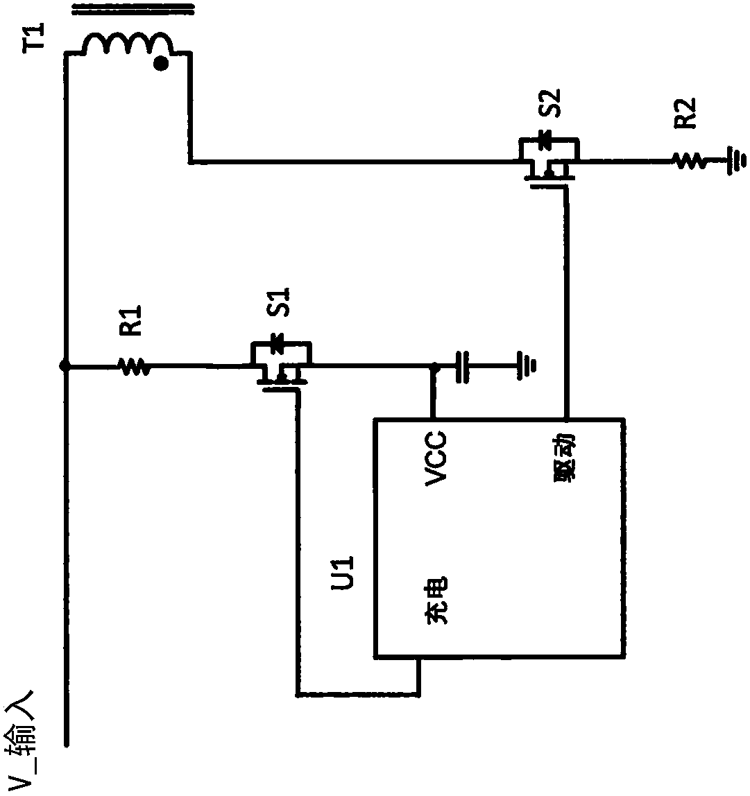
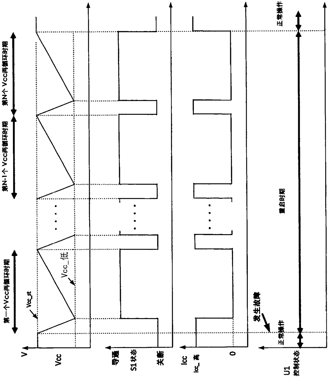
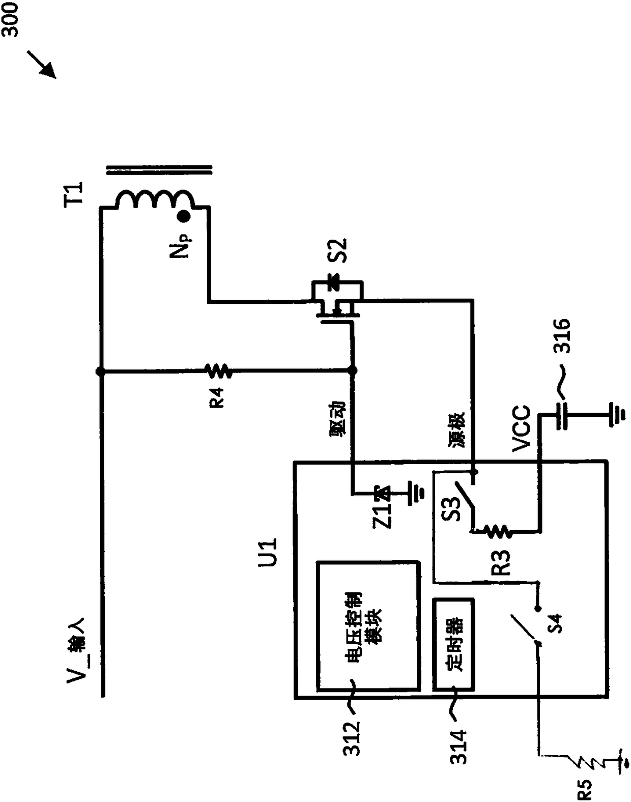
[0016] The following discussion will focus on flyback converters. However, it will be appreciated that the improved restart period disclosed herein may be implemented in other types of switching power converters, such as buck converters, boost converters, or buck-boost converters. exist image 3 An example flyback converter 300 configured for a restart period independent of input voltage is shown in . As is known in the field of flyback converters, the flyback converter 300 includes a power switch transistor S2 in series with the primary winding of a transformer T1, a control configured to control the on and off states of the power transistor switch S2. device U1. During normal operation, the on and off states of the power switching transistor S2 are controlled by the drive terminal of the controller U1 coupled to the gate of the power switching transistor S2, and the controller U1 can maintain the output to the flyback converter 300 voltage output regulation (for simplicit...


PUM


Abstract

A power switch transistor for a switching power converter is maintained on during a re-startup period by a zener breakdown voltage following a fault condition for the switching power converter. A source voltage from the power switch transistor is used to charge a VCC capacitor that stores a power supply voltage for a controller for the switching power converter.

Description

[0001] Cross References to Related Applications [0002] This application claims priority and benefit to U.S. Provisional Patent Application No. 62 / 446,344, filed January 13, 2017, which is hereby incorporated by reference in its entirety. technical field [0003] This application relates to switching power converter controllers, and more particularly to switching power converter controllers with active start-up timing control. Background technique [0004] The high efficiency of switching power converters such as flyback converters has led to their virtually universal suitability as battery chargers for mobile devices. Because flyback converters convert AC household voltage, fault conditions such as short circuits can be potentially dangerous. It is thus common for flyback converter controllers to monitor various fault conditions. If the controller detects that a fault condition exists, it stops cycling the power switches and enters a restart period. At the end of the re...

Claims


Application Information

Patent Timeline
Patent Type & Authority Applications(China)
IPC IPC(8): H02M1/36
CPCH02M1/36H02M1/32H02M3/33507H02M1/0006H02M1/322
Inventor 冯光孔鹏举K-W·金彭明生
Owner DIALOG SEMICONDUCTOR GMBH
Learn More