Cooling device for laser welding

A cooling device and laser welding technology, applied in laser welding equipment, welding equipment, metal processing equipment, etc., can solve the problem of polluting the lens and achieve the effect of preventing temperature rise

Pending Publication Date: 2018-07-24
合肥市弘泽机械加工有限公司
View PDF0 Cites 2 Cited by
  • Summary
  • Abstract
  • Description
  • Claims
  • Application Information

AI Technical Summary

Problems solved by technology

The cavity acts as an annular air channel to form an air curtain around the laser welding nozzle to prevent dust from entering the laser beam channel and polluting the lens. Tube cooling to prevent the temperature rise of the laser beam during the transmission of the laser channel, resulting in changes in the laser mode and affecting the welding quality

Method used


Image

  • Cooling device for laser welding
  • Cooling device for laser welding
  • Cooling device for laser welding

Examples


Embodiment Construction

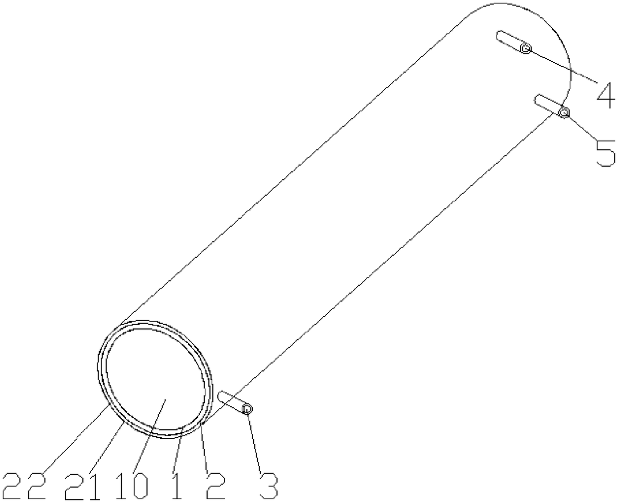
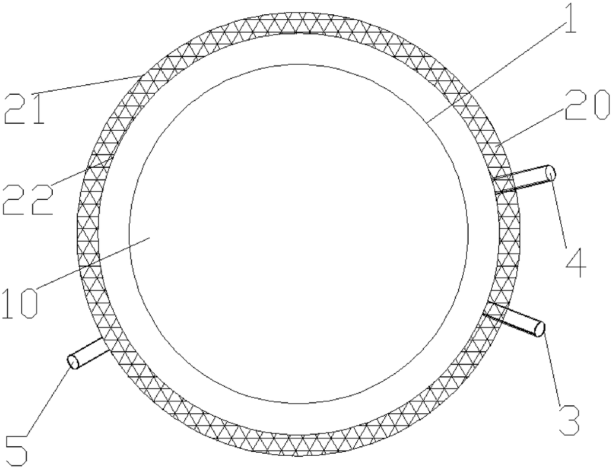
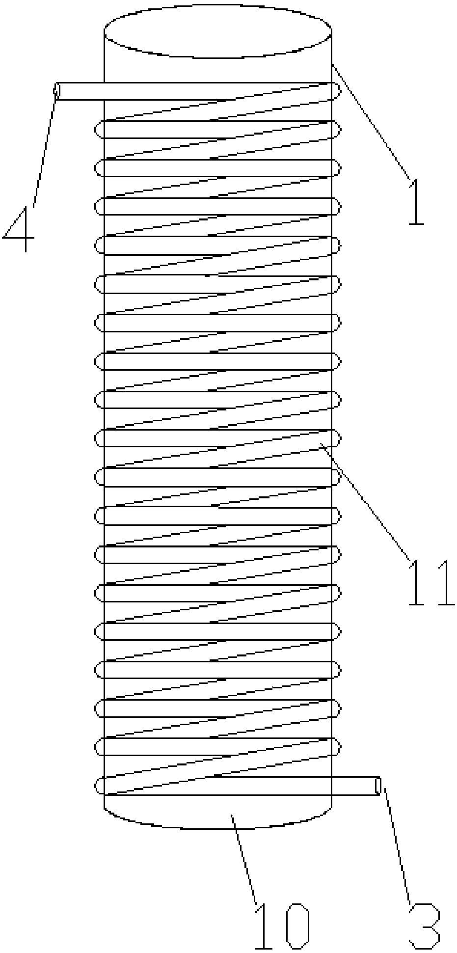
[0018] Such as Figure 1 to Figure 4 As shown, a cooling device for laser welding includes a light pipe 10, a cavity 2, a water inlet pipe 3, an outlet pipe 4, and an air intake pipe 5. The light pipe 10 is composed of a light pipe shell 1; the light pipe shell There is a coil pipe 11 outside the body 1; the coil pipe 11 is a half pipe and the lower part is connected with the water inlet pipe 3, and the upper part is connected with the water outlet pipe 4; the cavity 2 is formed as an annular air channel by the cavity outer wall 21 and the cavity inner wall 22; The upper part of the outer wall 21 of the cavity is connected with the air intake pipe 5; the cavity 2 is closely connected with the coil tube 11, and the lower part of the cavity is provided with an isolation net 20.

[0019] According to the above-mentioned structure, when the laser welding machine is working, the cooling device of laser welding is connected with the laser generator 30 and the laser welding nozzle 40...


PUM

PropertyMeasurementUnit
Mesh diameteraaaaaaaaaa
Diameteraaaaaaaaaa

Abstract

The invention discloses a cooling device for laser welding. The cooling device comprises a light-transmitting pipe, a hollow, a water inlet pipe, a water outlet pipe and an air inlet pipe. The light-transmitting pipe is composed of a light-transmitting pipe shell. A coil pipe is arranged outside the light-transmitting pipe shell. The coil pipe is a half pipe, the lower portion of the coil pipe isconnected with a water inlet pipe, and the upper portion of the coil pipe is connected with a water outlet pipe. The cavity serves as an annular air channel, and is formed by a cavity outer wall and acavity inner wall. The upper portion of the cavity outer wall is connected with the air inlet pipe. The cavity is closely connected with the coil pipe, and an isolating screen is arranged on the lower portion of the cavity. The cavity serves as the annular air channel, and an air curtain is formed around a laser welding nozzle, and dust is prevented from entering a laser beam channel to contaminate a lens. Meanwhile, a welded workpiece can be purged, and the problem of weld porosity caused due to the fact that a workpiece is not cleared up is avoided; and in cooperation coil pipe cooling, thesituation that the temperature rises in the transmission process of laser beams in a laser channel is avoided, and consequently the laser mode changes, and the welding quality is influenced is avoided.

Description

technical field [0001] The invention belongs to the field of laser welding equipment, in particular to a cooling device for laser welding. Background technique [0002] Laser welding is a new type of welding method, mainly aimed at the welding of thin-walled materials and precision parts. The weld seam is smooth and beautiful, the quality of the weld seam is high, there is no air hole, it can be precisely controlled, the focusing spot is small, the positioning accuracy is high, and it is easy to realize. Automation, so laser welding machines have been widely used in many fields. [0003] Traditional laser welding has always had problems that are difficult to solve, that is, after a period of welding, the welding quality will deteriorate, and in severe cases, the welding work will not be able to be carried out. There are three main reasons for this: First, dust enters the laser channel during the welding process , pollute the lens, reduce the reflectivity, and affect the las...

Claims


Application Information

Patent Timeline
IPC IPC(8): B23K26/70
CPCB23K26/703
Inventor 李强陈江浩
Owner 合肥市弘泽机械加工有限公司
Why Eureka
Try Eureka