Mechanical hole puncher for power construction

A technology of mechanical drilling and electric construction, applied in metal processing and other directions, can solve the problems of easy vibration of the punching machine, deviation of punching position, low punching quality, etc., so as to avoid different linear speeds and reduce deviation. The effect of improving safety and rationality

Inactive Publication Date: 2018-07-24
徐婧
View PDF0 Cites 6 Cited by
  • Summary
  • Abstract
  • Description
  • Claims
  • Application Information

AI Technical Summary

Problems solved by technology

[0006] Aiming at the deficiencies of the prior art, the present invention provides a mechanical drilling machine for electric power construction, which is equipped with a specified depth for drilling, the drill bit is pushed forward evenly, and the end of the drill bit is equipped with a buffer device to improve the drilling quality of the drill bit and service life, clamping the connection, time-saving and convenient, single-person operation, good punching quality, etc., solves the problem that the punching machine is prone to vibration during the punching process, causing the punching position to shift, and the punching problem During the process, the drill bit is pressed manually, and the uneven pressure may easily cause the drill bit to break. When drilling a threaded hole with a certain depth, it is easy to break through the connecting piece through artificial visual observation. , the connectors often need to be fixed, the artificial fixation effect is poor, and it is easy to cause the problem of low punching quality

Method used


Image

  • Mechanical hole puncher for power construction
  • Mechanical hole puncher for power construction
  • Mechanical hole puncher for power construction

Examples


Embodiment Construction

[0034] The following will clearly and completely describe the technical solutions in the embodiments of the present invention with reference to the accompanying drawings in the embodiments of the present invention. Obviously, the described embodiments are only some, not all, embodiments of the present invention. Based on the embodiments of the present invention, all other embodiments obtained by persons of ordinary skill in the art without making creative efforts belong to the protection scope of the present invention.

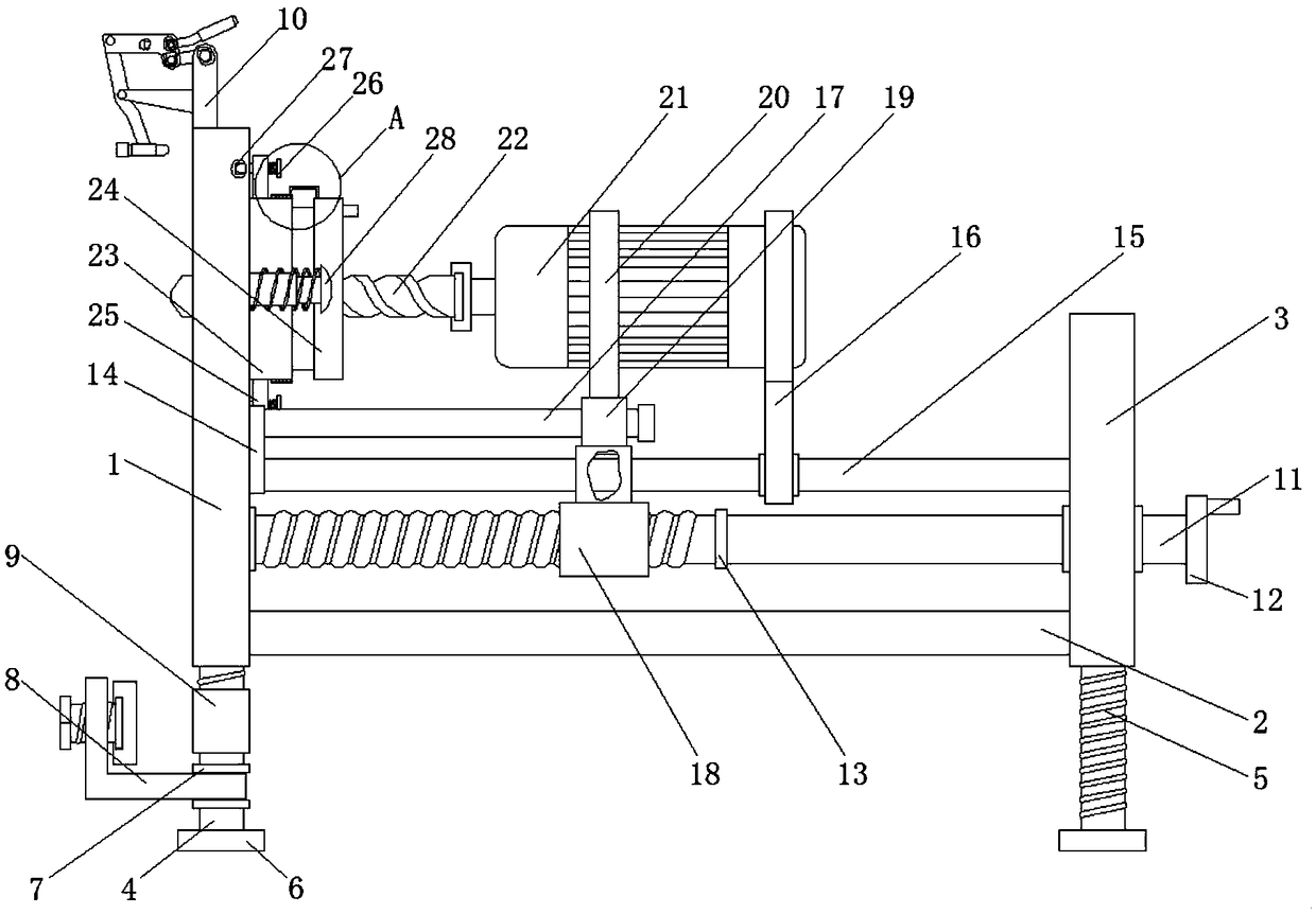
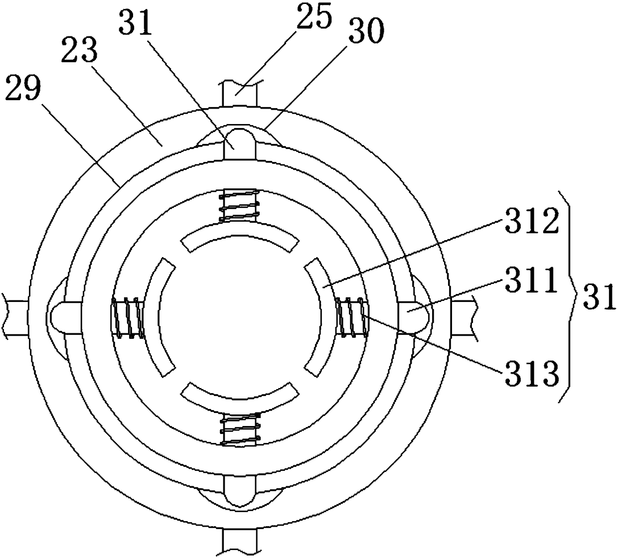
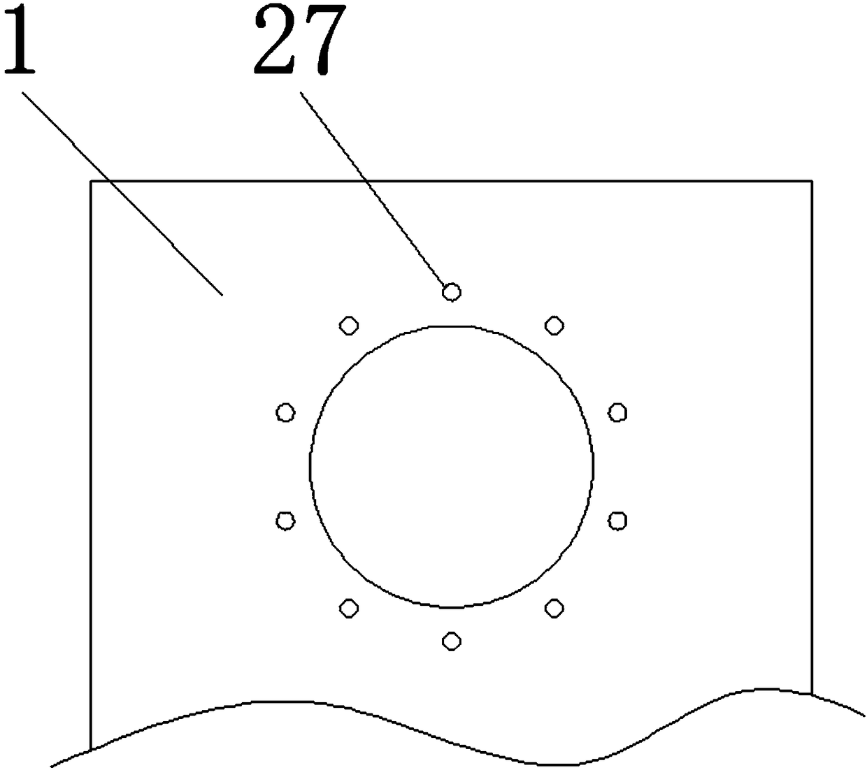
[0035] see Figure 1-9 , a mechanical punching machine for electric power construction, including a support plate I1, the bottom of one side of the support plate I1 is fixedly connected with the support plate II3 through the connection plate 2, and the bottoms of the support plate I1 and the support plate II3 are respectively threaded with bolt rods 4 and the support bolt 5, the bottom ends of the bolt rod 4 and the support bolt 5 are all fixedly connected wit...


PUM


Abstract

The invention relates to the technical field of power construction equipment and discloses a mechanical hole puncher for power construction. The mechanical hole puncher comprises a support plate I, wherein a support plate II is fixedly connected with the bottom of one side of the support plate I through a connecting plate; a bolt rod and a support bolt are in threaded connection with the bottoms of the support plate I and the support plate II respectively; support pads are fixedly connected with the bottom ends of the bolt rod and the support bolt; the middle of the bolt rod is fixedly connected in a sleeving manner with a fixing rod sleeve positioned above the support pads; the middle of the fixing rod sleeve is moveably sleeved with a compacting device. According to the mechanical hole puncher for power construction, an adjusting handle is lifted upwards, a connecting rod III is driven by a connecting II to rotate, furthermore a propping block is driven to extrude a workpiece to be processed through variations of inclination angles of the connecting rod III, one end of the workpiece to be processed can be fixed, the other end of the workpiece to be processed can be also fixed through the compacting device, then holes can be punched conveniently, the fixation stability of the workpiece to be processed can be improved, and the hole punching efficiency and quality can be improved.

Description

technical field [0001] The invention relates to the technical field of electric power construction equipment, in particular to a mechanical punching machine for electric power construction. Background technique [0002] Electric power engineering refers to projects related to the production, transmission and distribution of electric energy. In a broad sense, it also includes projects that use electricity as power and energy in various fields. Electric energy has gradually replaced steam power because it is easy to convert, transmit and control. It has become the technical foundation of material civilization and spiritual civilization in modern society. [0003] Electric power construction sites often need to combine multiple connectors together, and then thread-lock the threaded holes on the connectors through multiple sets of bolts. During installation, it is often caused by the offset of the installation position. The threaded holes on the two connecting pieces are not co...

Claims


Application Information

Patent Timeline
Patent Type & Authority Applications(China)
IPC IPC(8): B26F1/16B26D7/02B26D7/22B26D7/26
CPCB26F1/16B26D7/02B26D7/22B26D7/2628
Inventor 徐婧黄蕾姚田田
Owner 徐婧
Why Eureka
Try Eureka