Solar aviation obstruction light

An aviation obstruction light and solar energy technology, which is applied in the field of aviation obstruction lights, can solve the problems of easy damage and shortened service life of solar panels, and achieve the effect of ensuring efficient conversion and utilization, avoiding shortening of service life and ensuring structural stability.

Inactive Publication Date: 2018-07-24
HENAN CHANGMING HANGBIAO ELECTROMECHANICAL EQUIP CO LTD
View PDF0 Cites 2 Cited by
  • Summary
  • Abstract
  • Description
  • Claims
  • Application Information

AI Technical Summary

Problems solved by technology

[0004] The purpose of the present invention is: in order to solve the problem that the solar panel is fixed and external in the existing solar aviation obstruction light, which causes the solar panel to be easily damaged and shorten its service life when exposed to the outside for a long time, the present invention provides a solar energy aviation obstruction light

Method used


Image

  • Solar aviation obstruction light
  • Solar aviation obstruction light

Examples


Embodiment 1

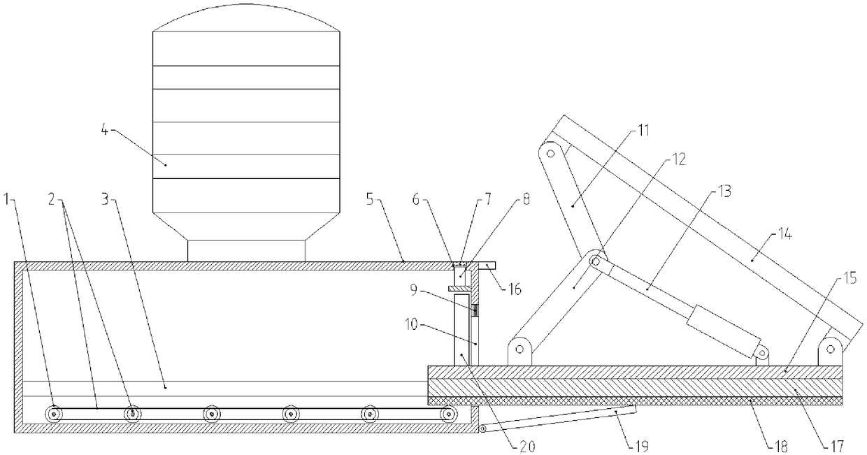
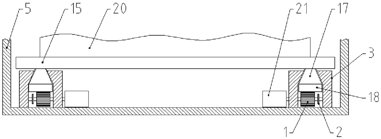
[0024] A solar aviation obstruction light, comprising a box body 5 with an obstruction light 4 installed on the top, a horizontal flat plate 15 is arranged inside the box body 5, a solar panel mechanism is arranged on the upper surface of the flat plate 15, and horizontal panels are arranged on both sides of the lower surface of the flat plate 15. The section is a tapered sliding bar 17, the bottom of the sliding bar 17 is provided with a rack 18, the inner bottom of the box body 5 is provided with a guide groove 3 cooperating with the sliding bar 17, the upper part of the guide groove 3 cross-section is conical, and the lower part is rectangular. The bottom of the guide groove 3 is provided with a number of gears 1 that cooperate with the rack 18. Several gears 1 are connected by a sprocket chain mechanism 2, and one of the gears 1 is connected with a driving motor 21. One side of the box body 5 is provided with an opening for the plate 15 to enter and exit. 10.

[0025] The ...

Embodiment 2

[0027] This embodiment improves on the basis of Embodiment 1:

[0028] The solar panel mechanism includes a solar panel 14, one end of the solar panel 14 is hinged on the upper surface of one side of the flat panel 15, and the other end of the solar panel 14 is hinged to the upper surface of the other side of the flat panel 15 through successively hinged connecting rods a11 and b12, and the solar panel 14 An electric telescopic rod 13 is arranged on the upper surface of the flat plate 15 below, and one end of the electric telescopic rod 13 is hinged on the upper surface of the flat board 15, and the other end of the electric telescopic rod 13 is hinged at the junction of the connecting rod a11 and the connecting rod b12.

[0029] The advantages of the above improvements are: the electric telescopic rod in the solar panel mechanism can be stretched, and the solar panel can be controlled to stand up and down through the connecting rod a and the connecting rod b, and the inclinati...

Embodiment 3

[0031] This embodiment improves on the basis of Embodiment 1:

[0032] A vertical baffle 20 is arranged on the upper surface of one side of the plate 15 , and the height of the baffle 20 is higher than the highest point of the opening 10 .

[0033] The advantages of the above improvements are: the baffle plate ensures that the plate will not be displaced excessively, so that the sliding bar on the plate is always located in the guide groove, ensuring the structural stability of the mechanism.


PUM


Abstract

The invention discloses a solar aviation obstruction light and relates to the technical field of an aviation obstruction light. The problems, in the existing solar aviation obstruction light, that a solar panel is exposed outside for a long time and has high probability of damage and the service life of the solar panel is shortened because the solar battery panel is fixed outside are solved. The solar aviation obstruction light comprises a box body; an obstruction light is arranged at the top of the box body; a horizontal flat plate is arranged in the box body; a solar panel mechanism is arranged on the upper surface of the flat plate; sliding strips with conical cross sections are arranged on the two sides of the lower surface of the flat plate correspondingly; racks are arranged at the bottoms of the sliding strips; a guide groove matched with the sliding strips is formed at the inner bottom of the box body; the upper part of the cross section of the guide groove is conical and the lower part of the cross section of the guide groove is rectangular; a plurality of gears matched with the racks are arranged at the bottom of the guide groove; the plurality of gears are connected through a chain wheel and chain mechanism; one of the gears is connected with a driving motor; and an opening for the flat plate to exit and enter is formed in one side of the box body.

Description

technical field [0001] The invention relates to the technical field of aviation obstruction lights, in particular to a solar energy aviation obstruction light. Background technique [0002] Aviation obstruction light, also known as navigation aid lighting equipment, is a special lamp for marking obstacles. It is a special lamp used to remind aircraft pilots. It is usually installed on tall buildings, towers or other tall buildings, which can emit light at night. Display the outline and height of the building, which is convenient for the aircraft pilot to identify, so as to prevent the aircraft from colliding with the building. Traditional aviation obstruction lights are powered by external circuits, and cannot be used once the power fails, so aviation obstruction lights using solar energy appeared later. [0003] Conventional solar aviation obstruction lights use fixed external solar panels. Although solar energy can be collected and utilized, only in sunny weather can the ...

Claims


Application Information

Patent Timeline
Patent Type & Authority Applications(China)
IPC IPC(8): F21S9/03F21V23/00F21V33/00F21V15/015
CPCF21S9/032F21V15/015F21V23/02F21V33/00
Inventor 任延超
Owner HENAN CHANGMING HANGBIAO ELECTROMECHANICAL EQUIP CO LTD
Why Eureka
Try Eureka