On-line fabric defect detection device for warp knitting machines

A warp knitting machine and point detection technology, which is applied in the direction of measuring devices, optical testing of flaws/defects, and material analysis through optical means, can solve problems such as increased detection system failures, background clutter, and product quality degradation, and reduce the number of cameras. Quantity, convenient and flexible installation, and simplified device structure

Pending Publication Date: 2018-07-24
HAINING CITY KEWEI IND ELECTRONICS SCI & TECH
View PDF5 Cites 20 Cited by
  • Summary
  • Abstract
  • Description
  • Claims
  • Application Information

AI Technical Summary

Problems solved by technology

[0005] With the increase of the number of cameras, the production cost of the entire equipment will be high, and it will increase the difficulty of on-site installation and debugging, and also affect the production efficiency of the factory. At the same time, the more the number of cameras, the higher the failure rate
[0006] Due to the limited mechanical position, the distance between the camera and the warp-knitted fabric is relatively long, resulting in unclear imaging of the camera, and many faint flaws cannot be judged, which reduces the detection rate of the testing equipment, increases the false detection rate, and reduces the production of the warp-knitting factory. efficiency and yield
[0007] If the fabric has an irregular pattern or a mesh fabric, the existing technology cannot detect fabrics with high light transmittance or very thick fabrics. This equipment is only suitable for those fabrics that are very thin and have a certain density, so for complex fabric textures There is no overall judgment ability, it can only detect and judge some simple fabrics, and the dynamic range of signal sensitivity is also very small, so it cannot pick up the slight changes on the fabric surface, and because it is a fixed position shooting, it can only be photographed Flat image, unable to achieve 3D stereoscopic imaging
[0008] In addition, it is unavoidable that the existing solutions exist: the camera is too far away from the fabric, the picture is not clear, the detection rate is reduced, and the false detection rate is increased; the installation of multiple cameras increases the production cost, increases the difficulty of installation and debugging, and increases the failure of the detection system; During the production process, the defect features are weak, and the camera angle is limited. The existing technology cannot be detected by multi-angle photography, and 3D stereoscopic images cannot be obtained. Many thick cloths cannot be detected at all; thin cloths are transparent and the background is messy, so they cannot be effectively Judgment of defective points, resulting in false stops; after the detection rate is low, manual visual inspection will work for a long time, and visual fatigue will occur, which will eventually lead to a decline in product quality, making it difficult to mass-produce, and the above problems will eventually lead to a serious decline in product quality. These problems

Method used


Image

  • On-line fabric defect detection device for warp knitting machines
  • On-line fabric defect detection device for warp knitting machines
  • On-line fabric defect detection device for warp knitting machines

Examples


Embodiment Construction

[0031] In order to make the purpose, technical solutions and advantages of this application clearer, the technical solutions in the embodiments will be clearly and completely described below in conjunction with the accompanying drawings in the embodiments. Obviously, the described embodiments are only a part of the application Examples, not all examples. Based on the given embodiments, all other embodiments obtained by persons of ordinary skill in the art without creative efforts fall within the protection scope of the present application.

[0032] In the description of the present application, it should be understood that the orientation or positional relationship indicated by the terms "upper", "lower" and the like is based on the orientation or positional relationship shown in the drawings, and is only for the convenience of describing the present application and simplifying the description, It is not intended to indicate or imply that the device or element referred to must...


PUM

PropertyMeasurementUnit
angleaaaaaaaaaa

Abstract

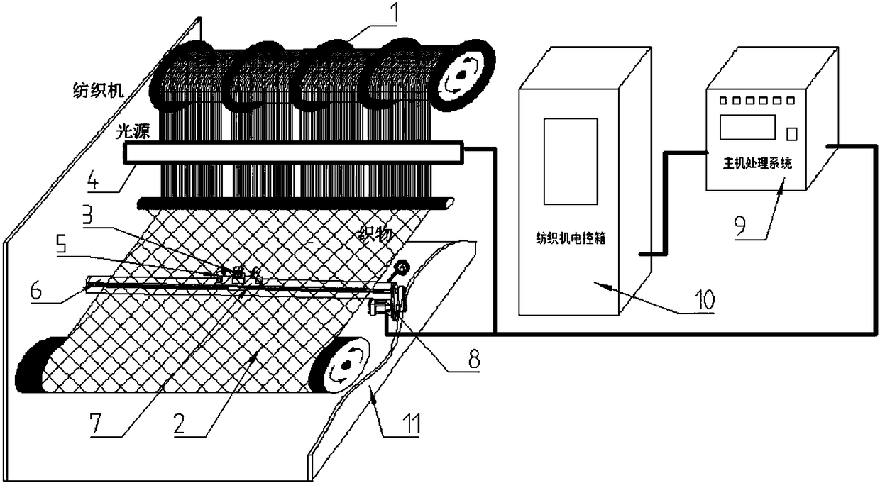
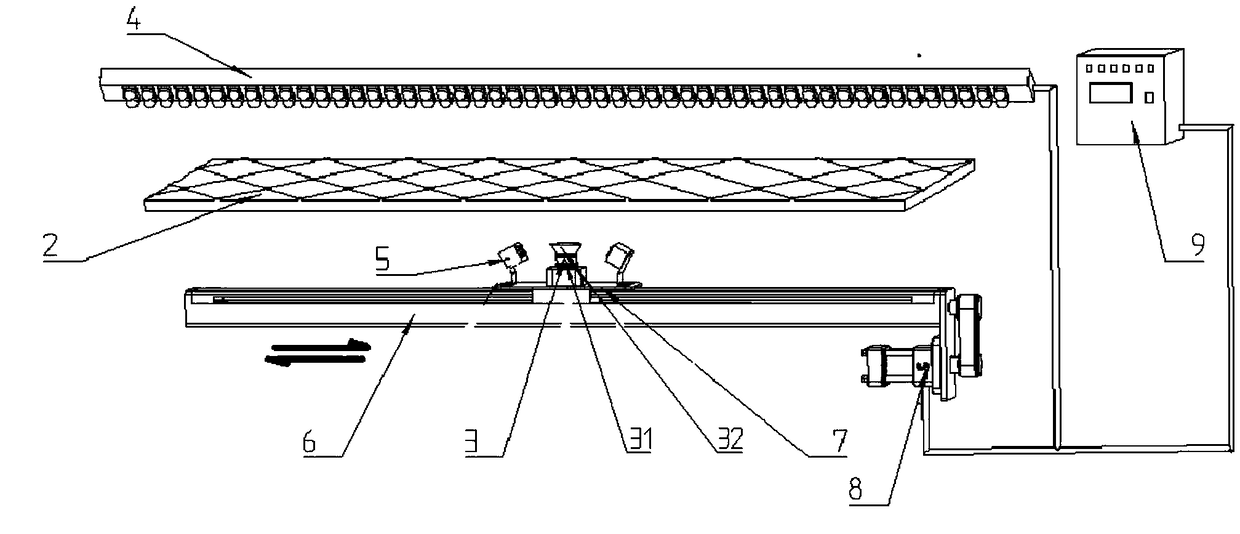
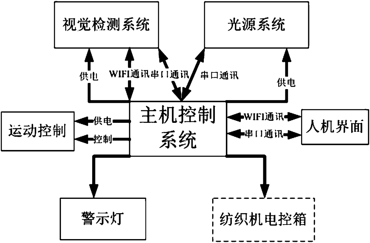
The invention discloses an on-line fabric defect detection device for warp knitting machines, which comprises a support assembly, a camera assembly, light sources, and a host control system. The on-line fabric defect detection device for warp knitting machines is characterized in that the light sources are a first light source and a second light source, the first light source is located over a fabric on a warp knitting machine, the supporting assembly comprises a guide way and a drive device, the drive device can drive the second light source and the camera assembly to synchronously slide to and fro along the guide way, the second light source and the camera assembly are located under the fabric on the warp knitting machine, and while sliding to and fro along the guide way, the camera assembly can acquire the image of the fabric; because the adopted moving shooting technique can shorten object distance, imaging quality can be ensured, and a good detection effect can be achieved. Sincethe moving shooting technique is adopted, the number of cameras is reduced, the on-line fabric defect detection device for warp knitting machines is convenient and flexible to mount, the structure ofthe device is simplified, the failure rate is low, multi-angle shooting can be carried out, the detection rate is greatly increased in comparison with the detection rate of the prior art, the false detection rate is greatly decreased, the labor intensity of workers is decreased, and the quality of products is greatly increased.

Description

technical field [0001] The invention belongs to the technical field of on-line detection devices for warp knitting fabric defects, and in particular relates to an on-line detection device for warp knitting machine fabric defects. Background technique [0002] Fabric defects refer to oil stains on the surface of the fabric, abnormal textures, fabric cracks due to thread breakage, changes in fabric density, holes, color differences, irregular protrusions and depressions, etc. are all defects. [0003] At present, the latest detection method applied in this field is mainly based on the camera fixed static detection system, mainly for the detection of relatively simple, thin and opaque fabrics. The existing camera fixed shooting detection working principle: a detection equipment according to the Dimensions, multiple cameras are installed at a fixed position more than 1 meter away from the fabric. Each camera continuously collects two-dimensional images of the fabric at a fixed ...

Claims


Application Information

Patent Timeline
Patent Type & Authority Applications(China)
IPC IPC(8): G01N21/89
CPCG01N21/8901G01N21/8914G01N2021/8908
Inventor 战学松
Owner HAINING CITY KEWEI IND ELECTRONICS SCI & TECH
Why Eureka
Try Eureka