Check patentability & draft patents in minutes with Patsnap Eureka AI!

Comparator-based communication power supply detection circuit

A technology of communication power supply and detection circuit, applied in the field of communication, can solve the problems of communication power supply detection, incomplete protection, increase equipment input cost, etc., and achieve the effects of avoiding long-term live operation, low equipment input cost, and preventing failures.

Pending Publication Date: 2018-07-24
成都众宜天成科技有限公司
View PDF0 Cites 1 Cited by
  • Summary
  • Abstract
  • Description
  • Claims
  • Application Information

AI Technical Summary

Problems solved by technology

[0004] In view of the above shortcomings, the purpose of the present invention is to provide a communication power detection circuit based on a comparator, which mainly solves the problems in the prior art of partial communication power detection, incomplete protection, and increased equipment investment costs.

Method used


Image

  • Comparator-based communication power supply detection circuit
  • Comparator-based communication power supply detection circuit
  • Comparator-based communication power supply detection circuit

Examples


Embodiment 1

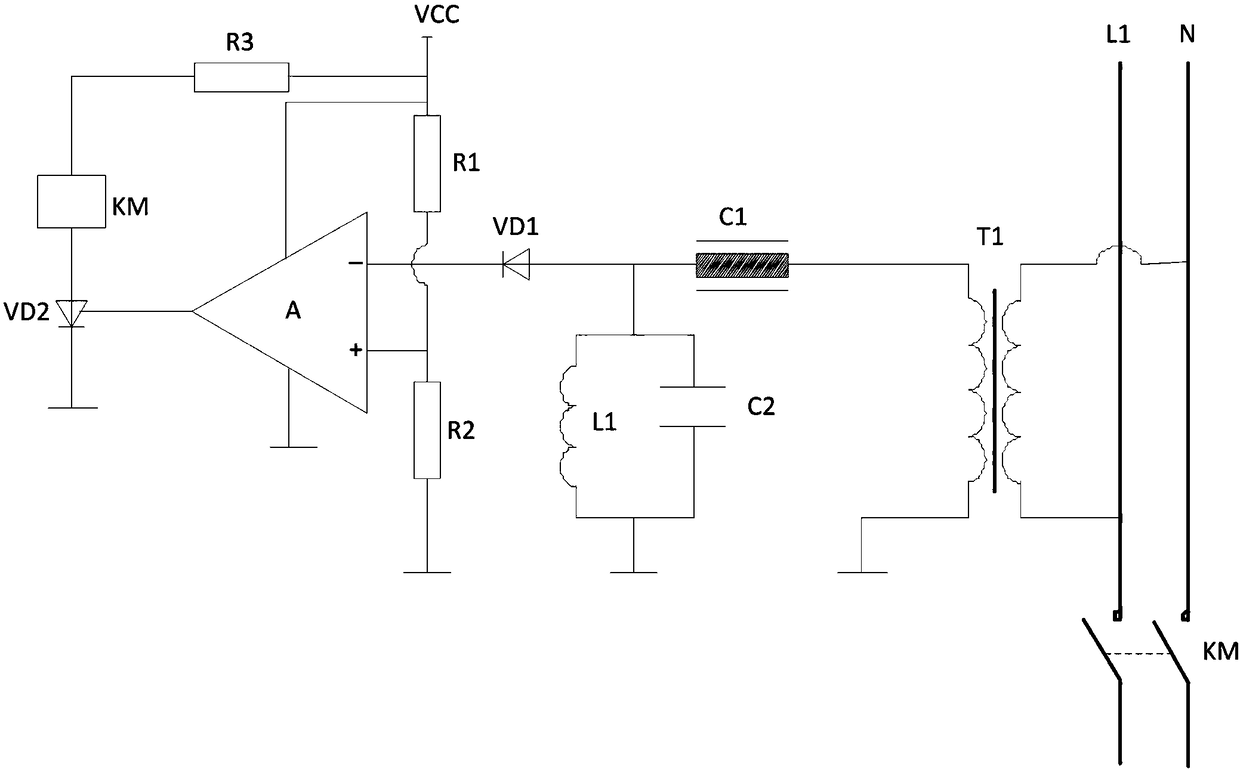
[0022] Such as figure 1 As shown, the comparator-based communication power supply detection circuit includes a contactor KM connected to the communication power supply with the main contact, a voltage transformer T1 connected in parallel to the communication power supply at the input end, and a voltage transformer T1 connected to an output terminal of the voltage transformer T1 Filter circuit, the input terminal is connected to the diode VD1 of the filter circuit, the input cathode is connected to the output terminal of the diode VD1 LM339N comparator A, one end is respectively connected to the input anode of the comparator A, and the resistor R1 and resistor R2 for voltage division are compared with The trigger circuit connected to the output terminal of the device A, and the resistor R3 connected to the external power supply VCC at one end, wherein, the other end of the resistor R3 is connected to the contactor KM, the trigger circuit is connected to the contactor KM, the oth...

Embodiment 2

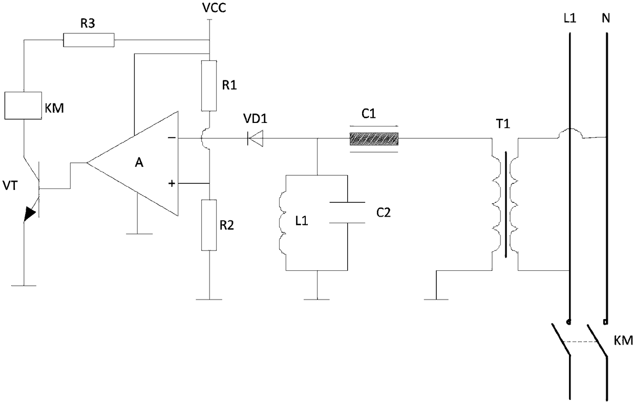
[0027] Such as figure 2 As shown, the detection circuit in this embodiment is further improved, and the difference from Embodiment 1 is that the trigger circuit is a triode VT of NPN structure, and the base of the triode VT is connected to the output pole of the comparator for controlling the The collector and emitter of the triode VT are turned on or off, the collector of the triode VT is connected to the contactor KM and the emitter is grounded.

Embodiment 3

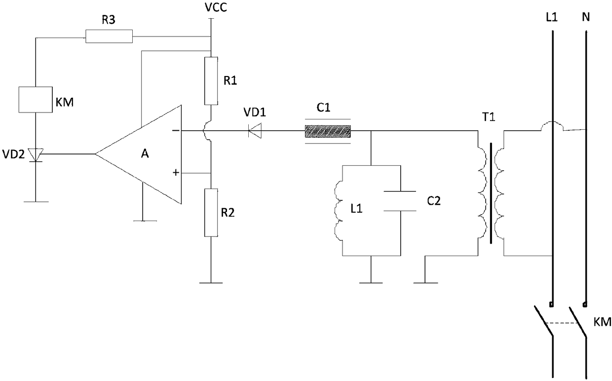
[0029] Such as image 3 As shown, the detection circuit in this embodiment is further improved, and the difference from Embodiment 1 is that the filter circuit of the detection circuit includes a capacitor C1 and a resonant circuit L1C2 with one end respectively connected to the output end of the voltage transformer T1, wherein , the other end of the resonant circuit L1C2 is grounded.

[0030] The present invention cleverly arranges a filter circuit, effectively isolates the carrier signal on the communication power line, and prevents the carrier signal from being strung into the detection circuit. In addition, on the premise of ensuring that the detection data is valid, the diode is set to pass through an effective detection voltage waveform to reduce the comparison workload of the comparator. In summary, the present invention has the advantages of simple structure, reliable detection, and low cost. Compared with traditional detection circuits, it has substantial characteris...


PUM

PropertyMeasurementUnit
Resistanceaaaaaaaaaa

Abstract

The invention discloses a comparator-based communication power supply detection circuit which mainly solves the problems existing in the prior art that part of communication power supplies are incomplete in detection and protection, and equipment input cost is increased. The detection circuit comprises a contactor KM, a voltage transformer T1, a filter circuit, a diode VD1, a comparator A, a resistor R1, a resistor R2, a trigger circuit and a resistor R3, wherein a main contact of the contactor is connected with the communication power supply; the input end of the voltage transformer T1 is connected in parallel with the communication power supply; the filter circuit is connected with an output end of the voltage transformer T1; the input end of the diode VD1 is connected with the filter circuit; an input negative pole of the comparator A is connected with an output end of the diode VD1; one ends of the resistor R1 and the resistor R2 are respectively connected with an input positive pole of the comparator A, and the resistors R1 and R2 are used for voltage division; the trigger circuit is connected with the output end of the comparator A; and one end of the resistor R3 is externally connected with a power supply VCC. According to the scheme, the comparator-based communication power supply detection circuit disclosed by the invention has the advantages of being simple in structure, reliable in detection, low in cost and the like, and has wide market prospects and popularization values in the technical field of communications.

Description

technical field [0001] The invention relates to the technical field of communication, in particular to a communication power detection circuit based on a comparator. Background technique [0002] The communication power supply is the key infrastructure of the entire communication network. The stability and reliability of the communication power supply is the key to ensure the safe and reliable operation of the communication system. The communication circuit is interrupted and the communication system is paralyzed, resulting in great economic and social benefit losses. Therefore, in order to ensure the reliable operation of communication equipment, important communication systems are powered by dual power supplies or an uninterruptible power supply system is added. Due to the cost of equipment investment, at present, some secondary communication power supplies are still powered by a single power supply, and the communication power supply is connected to the communication sys...

Claims


Application Information

Patent Timeline
IPC IPC(8): G01R31/40
CPCG01R31/40
Inventor 伍超辜晓平
Owner 成都众宜天成科技有限公司
Features
  • R&D
  • Intellectual Property
  • Life Sciences
  • Materials
  • Tech Scout
  • Unparalleled Data Quality
  • Higher Quality Content
  • 60% Fewer Hallucinations
Learn More