
Horizontal calibration method of isar image based on iaa spectral estimation technology

A spectral estimation and lateral technology, applied in the direction of radio wave reflection/reradiation, instruments, measuring devices, etc., can solve the problems of low ISAR lateral calibration accuracy, inaccurate target speed, target recognition, and inconvenient three-dimensional reconstruction. Achieve the effect of improving horizontal calibration results, saving calculation amount, and improving horizontal calibration accuracy

Active Publication Date: 2021-08-31
HARBIN INST OF TECH
View PDF6 Cites 0 Cited by
  • Summary
  • Abstract
  • Description
  • Claims
  • Application Information

AI Technical Summary

Problems solved by technology

[0006] The purpose of the present invention is to solve the problem that the target rotational speed estimated by the existing method is inaccurate, which leads to the low accuracy of ISAR lateral calibration and brings inconvenience to the subsequent target recognition and three-dimensional reconstruction, and proposes an ISAR based on IAA spectrum estimation technology Image Horizontal Scaling Method

Method used


Image

  • Horizontal calibration method of isar image based on iaa spectral estimation technology
  • Horizontal calibration method of isar image based on iaa spectral estimation technology
  • Horizontal calibration method of isar image based on iaa spectral estimation technology

Examples


specific Embodiment approach 1

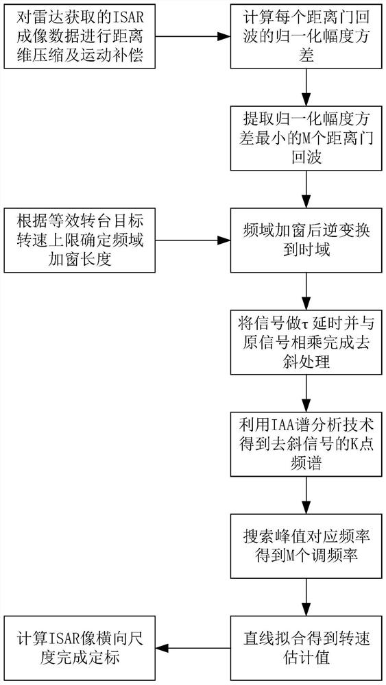
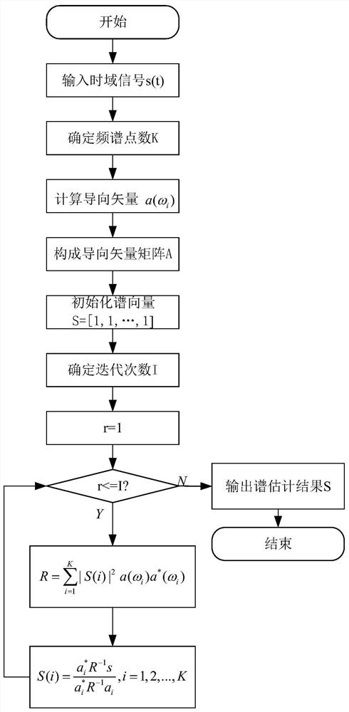
[0028] Specific implementation mode one: combine figure 1 , figure 2 To illustrate this embodiment, the specific process of the ISAR image horizontal calibration method based on IAA spectrum estimation technology in this embodiment is:

[0029] Step 1. Perform distance dimension compression and motion compensation on the ISAR imaging data acquired by the radar. After motion compensation, the ISAR observation target can be treated as a turntable target, and the ISAR imaging echo after motion compensation is approximately equivalent to the turntable target. Wave, that is, to obtain the ISAR imaging echo data of the turntable target, calculate the normalized amplitude variance of J range gate echoes, sort from small to large, and select M range gate echo signals with the smallest variance;

[0030] The ISAR is an inverse synthetic aperture radar; J is the number of range gates;

[0031] Step 2. Record the maximum longitudinal distance corresponding to the M range gate echo si...

specific Embodiment approach 2

[0074] Specific embodiment 2: The difference between this embodiment and specific embodiment 1 is that in the step 1, the ISAR imaging data obtained by the radar is compressed in the distance dimension and motion compensated. After the motion compensation, the actual observation target can be equivalent to a turntable target After processing, the ISAR imaging echo after motion compensation is approximately equivalent to the echo of the turntable target, that is, the ISAR imaging echo data of the turntable target is obtained, and the normalized amplitude variance of J range gate echoes is calculated, from small to large Sorting, selecting M range gate echo signals with the smallest variance; the specific process is:

[0075] Assuming that the radar transmits LFM signals, the ISAR imaging data obtained by the radar is compressed in the range dimension and motion compensated, and the ISAR imaging echo after motion compensation is approximately equivalent to the echo of the turntab...

specific Embodiment approach 3

[0097] Embodiment 3: This embodiment is different from Embodiment 1 or Embodiment 2 in that: the M is 8-10.

[0098] In the case that many range gates include scattering points, M can be set to 8-10.

[0099] Other steps and parameters are the same as those in Embodiment 1 or Embodiment 2.


PUM


Abstract

The invention relates to an ISAR image lateral calibration method based on IAA spectrum estimation technology, and the invention relates to a lateral calibration method of inverse synthetic aperture radar imaging. The purpose of the present invention is to solve the problem that the target rotational speed estimated by the existing method is inaccurate, which leads to the low accuracy of ISAR lateral calibration and brings inconvenience to subsequent target recognition and three-dimensional reconstruction. 1. Obtain the ISAR imaging echo data of the turntable target, calculate the normalized amplitude variance of all J range gate echoes, and select M range gate echo signals with the smallest variance; 2. Obtain the length of the spectrum plus window, window type is a rectangular window; 3. Obtain M range gate echo signals after preprocessing; 4. Obtain the angular frequency estimates of M de-ramping signals; 5. Obtain the estimated value of the rotational angular velocity of the equivalent turntable target; 6. Calculation The horizontal scale of the ISAR image is redrawn according to the horizontal scale to complete the horizontal calibration of the ISAR image. The invention is used in the field of radar imaging.

Description

technical field [0001] The invention relates to a lateral calibration method for inverse synthetic aperture radar imaging. Background technique [0002] ISAR imaging technology can obtain high-resolution two-dimensional images of ships, aircraft, satellites and other targets. The high resolution in the range direction is obtained by the large bandwidth of the transmitted signal, which is a known quantity without changing the bandwidth of the transmitted signal; while its azimuth (lateral) resolution is obtained through Doppler analysis, so the lateral unit scale is determined by the Doppler The resolution of the Le frequency domain is determined, and it changes with the target speed and accumulation time. Therefore, the two-dimensional ISAR image can only reflect the relative position of the scattering point in the azimuth direction. For subsequent processing such as target recognition and 3D reconstruction, it is necessary to perform horizontal calibration on the 2D image...

Claims


Application Information

Patent Timeline
Patent Type & Authority Patents(China)
IPC IPC(8): G01S13/90
CPCG01S13/904G01S13/9041G01S13/9064
Inventor 王勇黄鑫谢俊好李绍滨李高鹏
Owner HARBIN INST OF TECH
Learn More