
Antenna azimuth transition adjusting device

A technology of antenna azimuth and adjustment device, which is applied to antennas, transmission devices, electrical components, etc., can solve problems such as difficulties in manufacturing and engineering installation and maintenance, increase in the volume of transmission devices and antennas, and increase in cost and control difficulty, and achieve improved Reliability and accuracy, saving assembly time, avoiding insufficient switching effects

Active Publication Date: 2018-07-24
WUHAN HONGXIN TELECOMM TECH CO LTD
View PDF16 Cites 19 Cited by
  • Summary
  • Abstract
  • Description
  • Claims
  • Application Information

AI Technical Summary

Problems solved by technology

The azimuth of each frequency band in the multi-frequency antenna needs to use its own phase shifter. Usually, the phase shifter of each frequency band in the antenna corresponds to a separate controller, which leads to too many internal controllers in the antenna. Increased size of device and antenna
[0004] Since the communication interface and control interface increase proportionally with the increase in the number of frequency bands, the space at the bottom interface is tight, and manufacturing, engineering, installation and maintenance are difficult
With the integration and scarcity of antenna resources, electric-tunable base station antennas are developing in the direction of multi-frequency and miniaturization. The current lower end of the antenna has insufficient space in the layout under the condition of multi-frequency compatibility. At the same time, one frequency band corresponds to one electric The existing technical solution of the control device, due to the increase in the number of frequency bands, the cost and control difficulty increase accordingly

Method used


Image

  • Antenna azimuth transition adjusting device
  • Antenna azimuth transition adjusting device
  • Antenna azimuth transition adjusting device

Examples


Embodiment Construction

[0031] The following will clearly and completely describe the technical solutions in the embodiments of the present invention with reference to the accompanying drawings in the embodiments of the present invention. Obviously, the described embodiments are only some, not all, embodiments of the present invention. Based on the embodiments of the present invention, all other embodiments obtained by persons of ordinary skill in the art without making creative efforts belong to the protection scope of the present invention.

[0032] In describing the present invention, it is to be understood that the terms "center", "upper", "lower", "front", "rear", "left", "right", "vertical", "horizontal", The orientations or positional relationships indicated by "top", "bottom", "inner", "outer", etc. are based on the orientations or positional relationships shown in the drawings, and are only for the convenience of describing the present invention and simplifying the description, rather than in...


PUM


Abstract

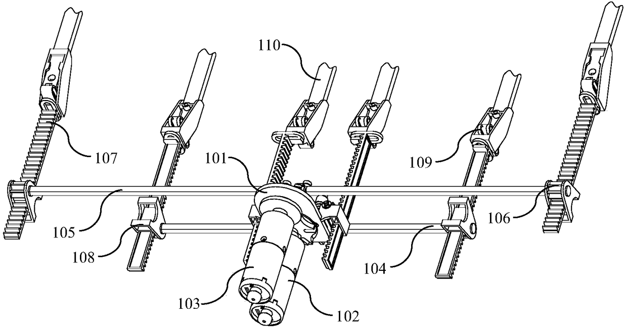
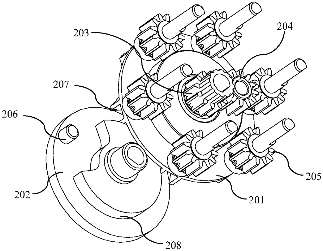
The invention provides an antenna azimuth transition adjusting device comprising a support frame (101), a power input motor (102), a power transition motor (103), a grooved pulley (201), a puller (202), a driving gear (203), a switching gear (204) and a driven gear (205); the power input motor (102) is directly or switched to be coaxially fixed with the grooved pulley (201); the power transition motor (103) is directly or switched to be coaxially fixed with the puller (202); the driving gear (203), the switching gear (204) and the driven gear (205) can form a gear set; a plurality of sets of worm and gear devices are arranged, and corresponding spur gears (106) and spur racks (107) are arranged so as to convert rotations into linear displacements. The grooved pulley and the worm and gearsare combined, thus changing a conventional mode of sun gear and planetary gear multistage gear drive, reducing parts number, saving assembling time, and reducing fault points.

Description

technical field [0001] The invention relates to the technical field of antennas, in particular to an antenna azimuth conversion and adjustment device. Background technique [0002] In a wireless communication system, the base station antenna is the interface between the transceiver and the external propagation medium. In the case that the physical position of the antenna of the base station remains unchanged, the phase shifters of each unit are connected in the antenna and the output phase of each phase shifter is controlled by an electronically controlled power output device through a transmission device. [0003] In the case of site sharing, in order to avoid installing too many antennas with different frequency bands at the same site and to reduce the load-bearing burden of the communication tower, a multi-frequency antenna integrating multiple frequency bands with one antenna is usually used. The azimuth of each frequency band in the multi-frequency antenna needs to use...

Claims


Application Information

Patent Timeline
Patent Type & Authority Applications(China)
IPC IPC(8): H01Q3/08F16H37/02
CPCF16H37/02H01Q3/08
Inventor 程季吴卫华张申科赖青松
Owner WUHAN HONGXIN TELECOMM TECH CO LTD
Learn More