
Intelligent wind-resistant solar battery cell mounting rack

A technology for solar cells and mounting frames, which is applied to solar thermal energy, solar collectors, and solar heating systems. The effect of wind damage

Pending Publication Date: 2018-07-24
TONGWEI SOLAR HEFEI
View PDF1 Cites 1 Cited by
  • Summary
  • Abstract
  • Description
  • Claims
  • Application Information

AI Technical Summary

Problems solved by technology

[0003] At present, the general way of installing solar modules is to use several bolts to fix the solar panel on the mounting bracket without other redundant protection measures. Under the long-term action of strong wind, the bolts are very easy to loosen, and the solar panel is loose or the bolts are loose. The phenomenon that the mounting bracket at the fixed place is torn has seriously affected the normal operation of the solar cells
[0004] Regarding the above-mentioned problems, the application document "one-way wind-resistant solar module installation frame" with the application publication number of CN 104579132A avoids direct wind damage to the solar module by setting the installation frame in a manner that can rotate according to the wind force, but , the scheme of this application document obviously has a more obvious defect: 1. In order to better absorb light energy when installing the solar cell, it needs to be set in the way of facing the sun, but after the rotatable mounting frame is rotated by the wind, The light-absorbing surface of the solar cell will deviate from the sunny side, which will affect the photoelectric conversion efficiency of the solar cell and cause a lot of economic losses

Method used


Image

  • Intelligent wind-resistant solar battery cell mounting rack
  • Intelligent wind-resistant solar battery cell mounting rack
  • Intelligent wind-resistant solar battery cell mounting rack

Examples


Embodiment Construction

[0027] The following will clearly and completely describe the technical solutions in the embodiments of the present invention with reference to the accompanying drawings in the embodiments of the present invention. Obviously, the described embodiments are only some, not all, embodiments of the present invention. Based on the embodiments of the present invention, all other embodiments obtained by persons of ordinary skill in the art without making creative efforts belong to the protection scope of the present invention.

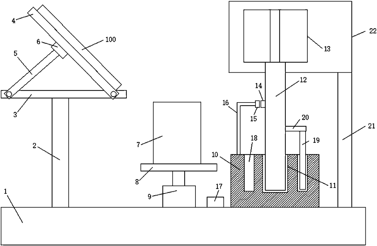
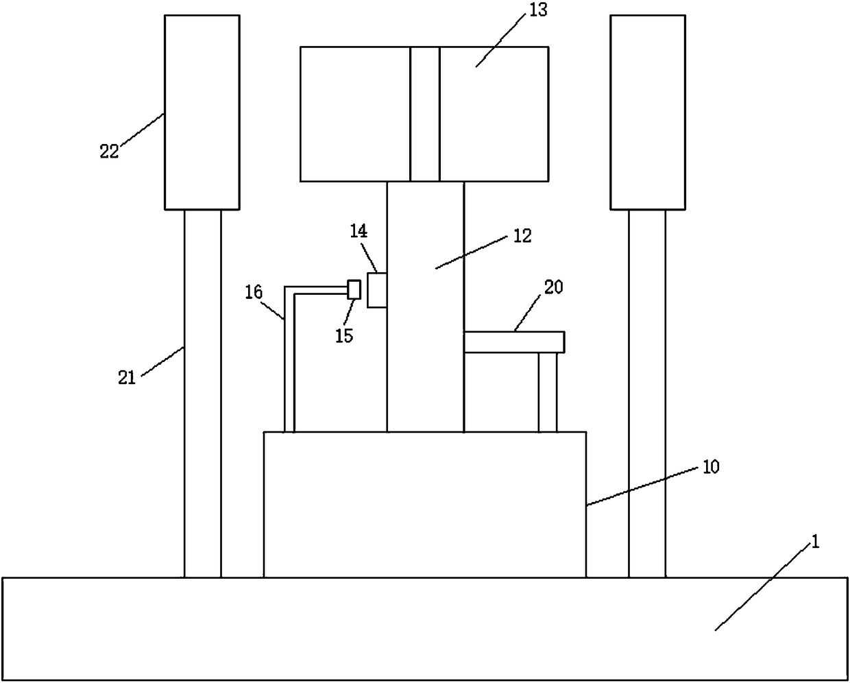
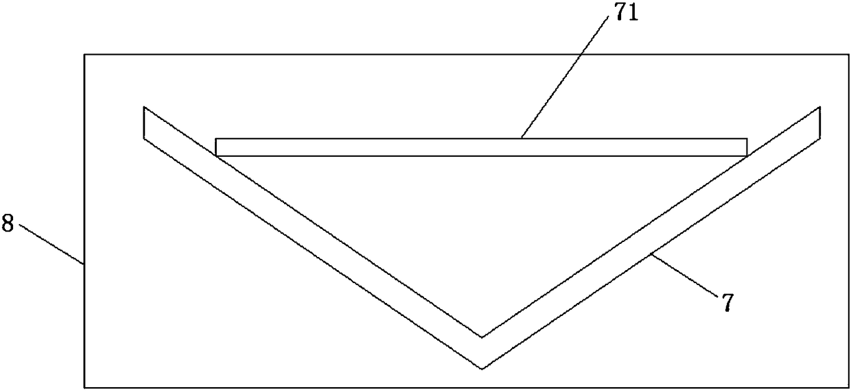
[0028] see Figure 1-4 , the present invention provides a technical solution:

[0029] An intelligent wind-resistant solar cell mounting frame, comprising a base plate 1, a mounting frame, a windshield 7 and a wind measuring block 10, a support column 2 is fixed on the base plate 1, and the support column 2 is vertically inserted on the base plate 1 to support A mounting frame is fixed on the end of the column 2 away from the substrate 1, and the mounting fra...


PUM


Abstract

The invention discloses an intelligent wind-resistant solar battery cell mounting rack. The intelligent wind-resistant solar battery cell mounting rack comprises a substrate, a mounting rack, a wind shield and a wind measurement block; a support column is fixed on the substrate, and the mounting rack is fixed at one end, far from the substrate, of the support column; the block measurement block isarranged on one side, far from the support column, of the wind shield; the wind measurement block is fixed on the substrate; an insertion slot is formed in the wind measurement block; a rotating shaft is movably inserted in the insertion slot; a fan blade is fixed at one end, far from the insertion slot, of the rotating shaft; a movable magnet is fixed on the rotating shaft; a revolving speed sensor is arranged on one side of the movable magnet; and the revolving speed sensor and an electric push rod are respectively and electrically connected on a singlechip. By measuring the wind power, thewind shield intelligently protects a solar battery cell, and the mounting rack remains stationary, so that the solar battery cell does not rotate the direction along with the wind power, the photoelectric conversion efficiency of the solar battery cell is also not affected, and huge economic loss is avoided.

Description

technical field [0001] The invention relates to the technical field of installing solar cells, in particular to an intelligent wind-resistant solar cell mounting frame. Background technique [0002] Today, when solar technology is widely used, the stability of solar module installation has attracted more and more attention. In order to ensure power generation efficiency, a certain angle between the module board and the ground should be maintained during installation, so as to facilitate the direct sunlight on the battery sheet, and the larger the angle is in low latitude areas. At present, solar module system stations are generally built in the Gobi area, where the wind and sand are relatively large and the working environment is relatively harsh. Faced with such an environment, solar modules undoubtedly become a windshield, and the wind force it bears is self-evident. [0003] At present, the general way of installing solar modules is to use several bolts to fix the solar ...

Claims


Application Information

Patent Timeline
Patent Type & Authority Applications(China)
IPC IPC(8): H02S20/30H02S40/00H02S40/30F24S30/425G01P5/07
CPCH02S20/30H02S40/00H02S40/30G01P5/07Y02E10/50
Inventor 谢泰宏谢毅周丹张冠纶张忠文
Owner TONGWEI SOLAR HEFEI
Learn More