Photovoltaic equipment bracket

A technology of photovoltaic equipment and support rods, which is applied to the support structure of photovoltaic modules, photovoltaic power generation, photovoltaic modules, etc., can solve the problems of high cost of photovoltaic equipment support, poor heat dissipation, poor stability, etc., to improve photovoltaic conversion efficiency and reduce The effect of power and support plate stability

Pending Publication Date: 2018-07-24
安吉晶圣光伏发电有限公司
View PDF8 Cites 3 Cited by
  • Summary
  • Abstract
  • Description
  • Claims
  • Application Information

AI Technical Summary

Problems solved by technology

[0004] In order to solve the defects of high cost, no energy saving, poor stability and poor heat dissipation of the photovoltaic equipment support existing in the prior art, the present invention provides a photovoltaic equipment support

Method used


Image

  • Photovoltaic equipment bracket
  • Photovoltaic equipment bracket

Examples


Embodiment Construction

[0015] In order to make the technical means, creative features, goals and effects achieved by the present invention easy to understand, the present invention will be further described below in conjunction with specific embodiments.

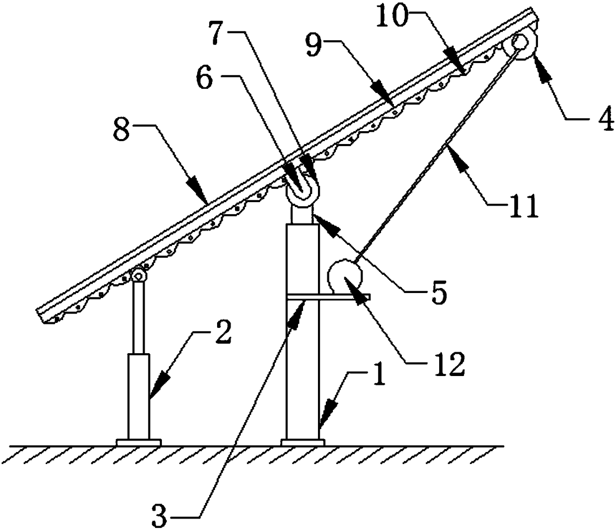
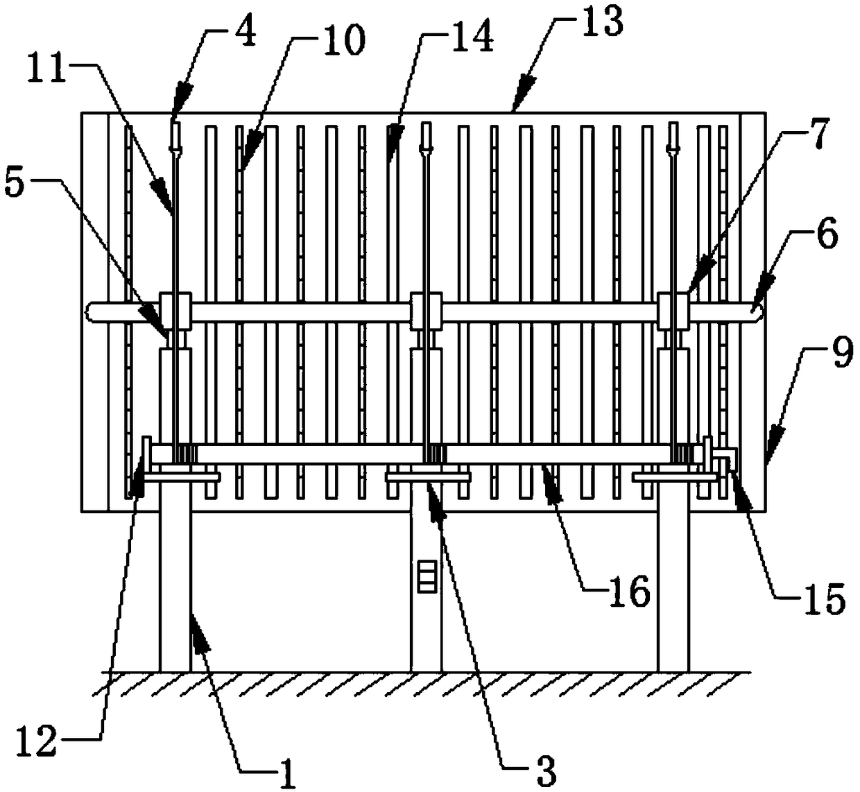
[0016] Such as Figure 1-2 As shown, a photovoltaic equipment bracket includes three support rods 1, three electric telescopic rods 2 and a support plate 13, and the tops of the three support rods 1 are fixedly provided with a fixed column 5, and the top ends of the fixed column 5 are fixedly provided with Collar 7, the inside of three collars 7 is interspersed with U-shaped fixed rod 6, and the two ends of U-shaped fixed rod 6 are fixedly connected with the middle part of two fixed bars 9 sides respectively, and the two fixed bars 9 are fixed A support plate 13 is provided, and a photovoltaic panel 8 is installed on one side of the support plate 13; Ring 4, the middle parts of the three support rods 1 are all fixedly provided with mounting plate...


PUM


Abstract

The invention discloses a photovoltaic equipment bracket which comprises three supporting rods, three electric telescopic rods and a supporting plate; fixed columns are fixedly arranged at the top ends of the three supporting rods, sleeve rings are fixedly arranged at the top ends of the fixed columns, a U-shaped fixed rod is connected with the insides of the three sleeve rings in a penetrating manner, the two ends of the U-shaped fixed rod are respectively and fixedly connected with the middles on one sides of two fixed strips, the supporting plate is fixedly arranged between the two fixed strips, a photovoltaic panel is mounted on one side of the supporting plate, and a plurality of heat dissipation strips and heat dissipation grooves are formed in the other side of the supporting plateat intervals. The photovoltaic equipment bracket disclosed by the invention has the benefits that through the design of the electric telescopic rods, one end of the supporting plate can be electrically driven to lift, therefore, the fixed angle of the supporting plate is flexibly changed, so that sunlight irradiation is more full, and the photovoltaic conversion efficiency is greatly improved; through the design that a supporting column is fixed at the center of the supporting plate, the flexible rotation of the supporting plate can be ensured; meanwhile, the power required is reduced, and thecost is lower.

Description

technical field [0001] The invention relates to a bracket, in particular to a photovoltaic equipment bracket. Background technique [0002] The photovoltaic equipment industry exists as a supporting industry for the photovoltaic industry. my country is the world's largest producer of solar cells. With the accumulation of rich technical experience, Chinese enterprises quickly achieved breakthroughs in the field of photovoltaic equipment. [0003] Photovoltaic panels need to be supported by brackets during installation. In order to ensure the strength of traditional photovoltaic equipment brackets, a relatively complicated mechanical structure is required. At the same time, in order to ensure the flexible change of the inclination angle of the bracket, a large power device is required, which increases the cost. , and in high temperature weather, the poor heat dissipation of the photovoltaic panel will affect the normal work and reduce the photoelectric conversion efficiency. T...

Claims


Application Information

Patent Timeline
Patent Type & Authority Applications(China)
IPC IPC(8): H02S20/30H02S40/42
CPCH02S20/30H02S40/42Y02E10/50
Inventor 施爱民
Owner 安吉晶圣光伏发电有限公司
Why Eureka
Try Eureka