Supercharge Your Innovation With Domain-Expert AI Agents!

Paste-in-hole printing device

A technology of solder paste printing and solder paste, applied in printing, printing machines, printing processes, etc., can solve the problems of insufficient soldering space, inability to guarantee quality, waste of time, etc., achieve good soldering effect, solve long soldering time, and unique design Effect

Pending Publication Date: 2018-07-24
欧朗电子科技有限公司
View PDF7 Cites 2 Cited by
  • Summary
  • Abstract
  • Description
  • Claims
  • Application Information

AI Technical Summary

Problems solved by technology

[0002] At present, the manual welding process is used for plug-in components, and the welding space is insufficient, and many points are easy to short circuit, resulting in unnecessary maintenance actions, which wastes time and cannot guarantee quality

Method used


Image

  • Paste-in-hole printing device
  • Paste-in-hole printing device

Examples


Embodiment Construction

[0020] In order to have a clearer understanding of the technical features, purposes and effects of the present invention, specific implementations are now described in detail.

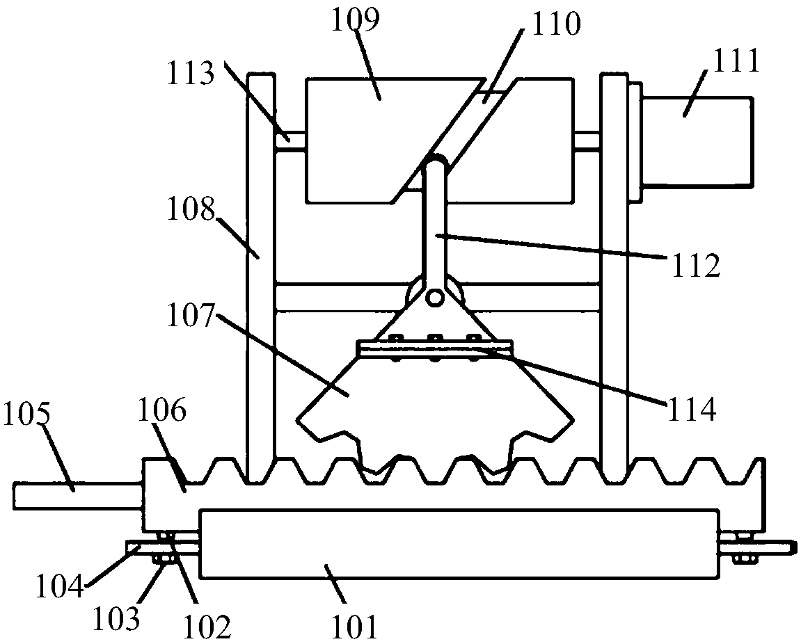
[0021] Such as figure 1 As shown, the through-hole solder paste printing device includes an X-Y axis motion platform 5 for carrying products and a stencil 3 matching the product, and through holes are opened on the stencil 3 corresponding to the parts on the product that need to fix components 7. The X-Y axis motion platform 5 is equipped with jigs for positioning and fixing the product 4 and the stencil 3. One side of the X-Y axis motion platform is arranged with a manipulator for picking and placing the product and the stencil, and a solder paste pushing unit is arranged above it 2. The solder paste pushing unit 2 includes a scraper seat and a bracket. The material of the bracket is aluminum alloy. The bracket includes two side bars and a beam installed on the top of the two side bars. A fixed horizo...


PUM


Abstract

The invention discloses a paste-in-hole printing device. The paste-in-hole printing device comprises an X-Y axis moving platform for carrying a product and a steel mesh matched with the product; a through hole is formed in the steel mesh corresponding to a part where a component needs to be fixed on the product; a fixture for locating and fixing the product and the steel mesh is arranged on the X-Y axis moving platform; a manipulator for taking and putting the product and the steel mesh is arranged on one side of the X-Y axis moving platform; a solder paste pushing unit is arranged above the manipulator and comprises a blade holder and a support; the support comprises two side rods and a cross beam which is horizontally arranged at the top ends of the two side rods; a fixed cross bar is horizontally arranged at the bottom ends of the two side rods; the blade holder is embedded into the fixed cross bar; the cross beam is arranged on a driving mechanism. Automatic printing and welding aswell as a good welding effect are realized; the steel mesh is designed for different positions and different sizes of bonding pads and the solder amounts required by the bonding pads with the different sizes are ensured, so that welding spots are molded to form a standard drum shape.

Description

technical field [0001] The invention relates to a through-hole solder paste printing device. Background technique [0002] At present, the manual welding process is used for the plug-in components. There is insufficient welding space, and many points are easy to short circuit, resulting in unnecessary maintenance actions, which wastes time and cannot guarantee quality. In response to this situation, it is necessary to make some changes from the perspective of product process design, and change the original hand-soldered components to solder paste process, that is, when SMT soldering, print solder paste, paste the components to the plug-in point, and then reflow soldering. In this way, the short circuit phenomenon caused by the welding point being too close and not easy to weld is avoided, and the welding quality can also be ensured. In this process, in addition to the change of product process design, it is necessary to design the steel mesh to meet the production requireme...

Claims


Application Information

Patent Timeline
Patent Type & Authority Applications(China)
IPC IPC(8): H05K3/34B41F15/08
CPCH05K3/34B41F15/08B41P2215/50H05K2203/0126
Inventor 张绍能
Owner 欧朗电子科技有限公司
Features
  • R&D
  • Intellectual Property
  • Life Sciences
  • Materials
  • Tech Scout
  • Unparalleled Data Quality
  • Higher Quality Content
  • 60% Fewer Hallucinations
Learn More