Heat dissipation device for filter

A technology of a heat dissipation device and a filter, applied in the field of filters, can solve the problems of low heat dissipation efficiency, prone to local high temperature, wasting time, etc., and achieve the effect of improving heat dissipation

Pending Publication Date: 2018-07-24
南京幕府信息技术有限公司
View PDF0 Cites 2 Cited by
  • Summary
  • Abstract
  • Description
  • Claims
  • Application Information

AI Technical Summary

Problems solved by technology

[0005] In order to solve the problem of low heat dissipation efficiency and time-wasting when heat dissipation is mentioned in the above background technology, and at the same time, the phenomenon of local high temperature is prone to occur during use; the purpose of the present invention is to provide a heat dissipation device for a filter

Method used


Image

  • Heat dissipation device for filter

Examples


Embodiment Construction

[0017] In order to make the object, technical solution and advantages of the present invention clearer, the present invention is described below through specific embodiments shown in the accompanying drawings. It should be understood, however, that these descriptions are exemplary only and are not intended to limit the scope of the present invention. Also, in the following description, descriptions of well-known structures and techniques are omitted to avoid unnecessarily obscuring the concept of the present invention.

[0018] Here, it should also be noted that, in order to avoid obscuring the present invention due to unnecessary details, only the structures and / or processing steps closely related to the solution according to the present invention are shown in the drawings, and the related Other details are not relevant to the invention.

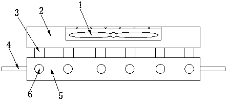
[0019] like figure 1 As shown, the specific embodiment adopts the following technical solutions: it includes a heat dissipation fan 1, a...


PUM


Abstract

The invention discloses a heat dissipation device for a filter and relates to the technical field of filters. A concave mounting groove is formed at the upper end of a heat dissipation seat body; a cooling fan is mounted in the mounting groove; a connecting heat dissipation fence is mounted at the lower end of the heat dissipation seat body; the bottom of the connecting heat dissipation fence is connected with a heat collection block; mounting frames are mounted at the two ends of the heat collection block; a plurality of heat dissipation pipe bodies in a Z-axis direction are arranged in the heat collection block; the device can achieve quick mounting, heat dissipation and heat collection, is high in efficiency, and can save time and achieve natural heat dissipation during use; and the heat dissipation capability is improved.

Description

Technical field: [0001] The invention belongs to the technical field of filters, and in particular relates to a cooling device for filters. Background technique: [0002] A filter is a filter circuit composed of capacitors, inductors and resistors. The filter can effectively filter the frequency point of a specific frequency in the power line or frequencies other than this frequency point to obtain a power signal of a specific frequency or eliminate a power signal of a specific frequency. A filter is a device or circuit that processes signals. Filters are divided into active filters and passive filters. The main function is: let the useful signal pass through without attenuation as much as possible, and attenuate the useless signal as much as possible. The filter generally has two ports, one input signal and one output signal. Using this feature, a square wave group or composite noise passing through the filter can be selected to obtain a sine wave of a specific frequency...

Claims


Application Information

Patent Timeline
Patent Type & Authority Applications(China)
IPC IPC(8): H05K7/20
CPCH05K7/20172H05K7/2039
Inventor 厉先象
Owner 南京幕府信息技术有限公司
Why Eureka
Try Eureka