Supercharge Your Innovation With Domain-Expert AI Agents!

Vibrating screen assembly and vibrating screen device

A technology of vibrating screen and components, applied in the direction of filter screen, solid separation, grid, etc., can solve the problems of high processing cost, unenvironmental protection, and high liquid content of drilling cuttings

Pending Publication Date: 2018-07-27
HEBEI GN SOLIDS CONTROL CO LTD
View PDF0 Cites 3 Cited by
  • Summary
  • Abstract
  • Description
  • Claims
  • Application Information

AI Technical Summary

Problems solved by technology

[0006] An object of the present invention is to provide a vibrating screen assembly to solve the technical problems of high liquid phase content in drill cuttings processed by the existing vibrating screen device, high processing cost and unenvironmental protection

Method used


Image

  • Vibrating screen assembly and vibrating screen device
  • Vibrating screen assembly and vibrating screen device
  • Vibrating screen assembly and vibrating screen device

Examples


Embodiment 1

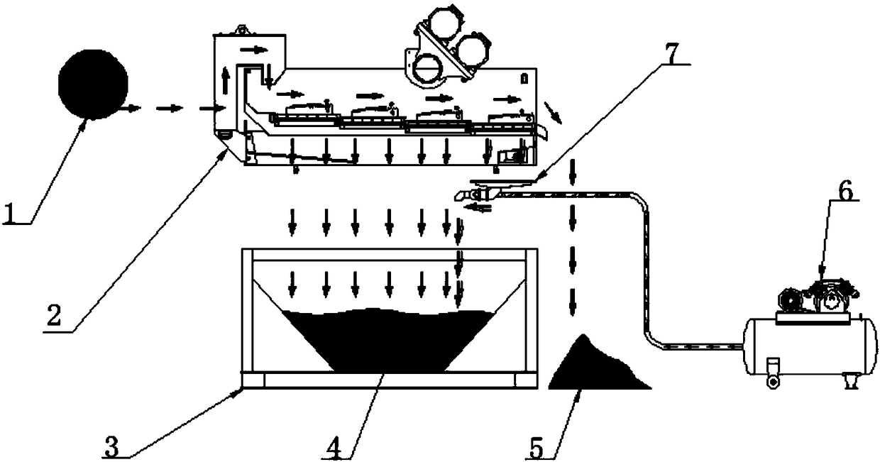
[0040] like Figure 1 to Figure 3 As shown, the vibrating screen assembly provided by the embodiment of the first aspect of the present invention includes: a vibrating screen 2 and a tank body 3, wherein a vacuum adsorption funnel arranged between the vibrating screen 2 and the tank body 3 is also included 7. Passing compressed air into the vacuum adsorption funnel 7 can generate negative pressure; the vibrating screen 2 includes a plurality of screens, and the vacuum adsorption funnel 7 is arranged corresponding to the screens.

[0041] The vibrating screen 2 assembly provided by the present invention also includes a vacuum adsorption funnel 7 arranged between the vibrating screen 2 and the tank body 3. Compressed air can be introduced into the vacuum adsorption funnel 7 to generate negative pressure. The adsorption funnel 7 can absorb the mud on the screen into the tank body 3, so that the liquid phase content in the cuttings 5 ​​is reduced, the moisture content of the cutti...

Embodiment 2

[0056] In any of the above technical solutions, further, a plurality of screens are evenly distributed along the feed port of the vibrating screen 2 to the discharge port, and the vacuum adsorption funnel 7 corresponds to the Screen settings. The funnel 22 of the vacuum adsorption funnel 7 can be arranged corresponding to the bottom of each screen.

[0057] Because the liquid phase content of the last sieve (at the outlet) is smaller than that of the previous sieve, it is not easy to separate. The best solution is to be provided with a vacuum adsorption funnel 7 at the bottom of the last sieve. The rest are the same as the first embodiment, and will not be repeated here.

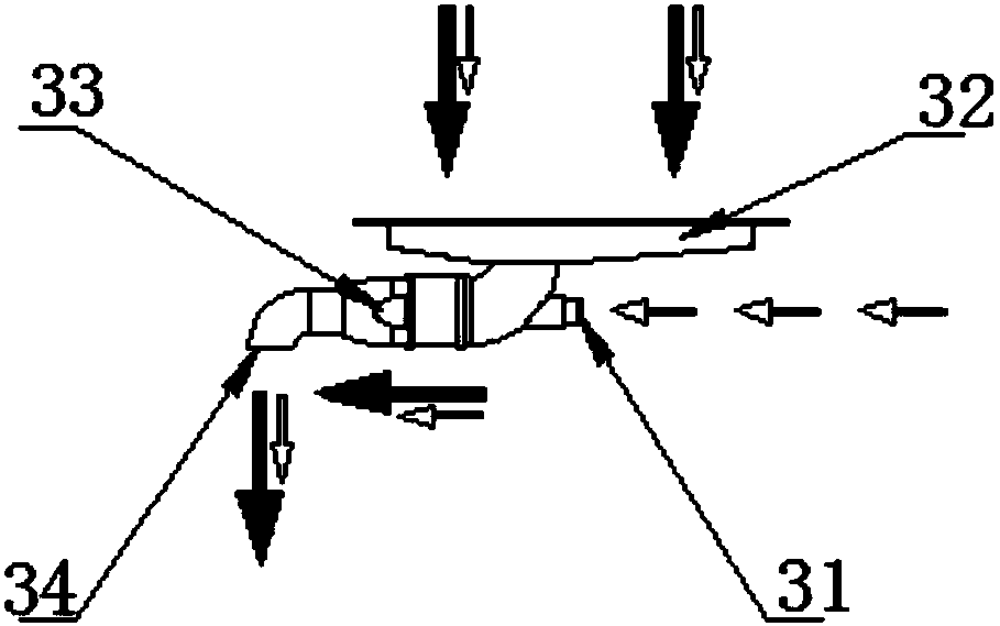
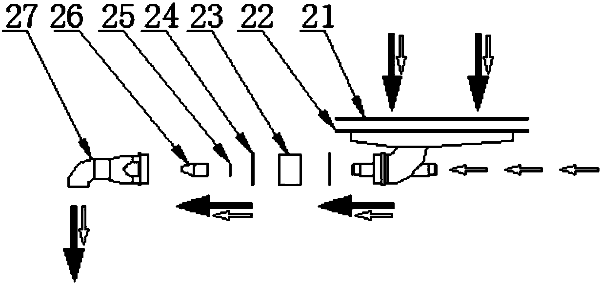
[0058] The vibrating screen 2 assembly provided by the present invention has the following working steps: using the Venturi principle of the nozzle 26, the compressed air produced by the air compressor 6 enters the negative pressure generating chamber 33 of the vacuum adsorption funnel 7, and the generated...


PUM


Abstract

The invention provides a vibrating screen assembly and a vibrating screen device and relates to the technical field of oil exploitation. The vibrating screen assembly comprises a vibrating screen anda tank body and further comprises a vacuum adsorption funnel arranged between the vibrating screen and the tank body, and compressed air is introduced into the vacuum adsorption funnel and can generate negative pressure. The vibrating screen comprises a plurality of pieces of screen cloth, and the vacuum adsorption funnel is arranged corresponding to the screen cloth. According to the vibrating screen assembly provided by the invention, mud on the screen cloth can be adsorbed into the tank body through the vacuum adsorption funnel, the liquid phase content in drilling cuttings can be lowered,the moisture content of the drilling cuttings is lowered, and the treatment cost of the drilling cuttings and influences on the environment are lowered.

Description

technical field [0001] The invention relates to the technical field of oil exploitation, in particular to a vibrating screen assembly and a vibrating screen device. Background technique [0002] During the use of the existing vibrating screen device, the untreated mud is divided into clean mud and drilling cuttings after being screened by the vibrating screen. The clean mud is collected into the tank below the vibrating screen, and the drilling cuttings are removed from the tank; [0003] Vibrating screen sieving treatment description: One or more screens are installed inside the vibrating screen. There are many small holes on the front of the screen. The liquid phase and mud smaller than the holes pass through the screen. On the screen surface, the separation is accelerated under the influence of vibration, and at the same time, the drill cuttings on the screen are excluded from the vibrating screen. [0004] The liquid phase content in the drill cuttings processed by the ...

Claims


Application Information

Patent Timeline
Patent Type & Authority Applications(China)
IPC IPC(8): B07B1/28
CPCB07B1/28
Inventor 周鹏先
Owner HEBEI GN SOLIDS CONTROL CO LTD
Features
  • R&D
  • Intellectual Property
  • Life Sciences
  • Materials
  • Tech Scout
  • Unparalleled Data Quality
  • Higher Quality Content
  • 60% Fewer Hallucinations
Learn More