
Rebar cutting-off device

A cutting device and steel bar technology, applied in the field of mechanical equipment, can solve problems such as uneven steel bars, lower work efficiency, accidental injuries of staff, etc., and achieve the effects of simple operation, improved work efficiency, and reduced labor intensity

Inactive Publication Date: 2018-07-27
合肥市硕理机电科技有限公司
View PDF5 Cites 0 Cited by
  • Summary
  • Abstract
  • Description
  • Claims
  • Application Information

AI Technical Summary

Problems solved by technology

[0003] At present, the traditional steel bar cutting machine does not have enough consideration for the fixed clamping device. During the cutting operation, the staff needs to hold the steel bar by hand, which will cause human errors to cause uneven cutting of the steel bar, and automatic clamping cannot be realized. , so that there will be safety hazards that may cause accidental injury to the staff during operation, and increase the labor intensity of the staff and reduce work efficiency

Method used


Image

  • Rebar cutting-off device
  • Rebar cutting-off device
  • Rebar cutting-off device

Examples


Embodiment Construction

[0021] The following will clearly and completely describe the technical solutions in the embodiments of the present invention with reference to the accompanying drawings in the embodiments of the present invention. Obviously, the described embodiments are only some, not all, embodiments of the present invention. Based on the embodiments of the present invention, all other embodiments obtained by persons of ordinary skill in the art without making creative efforts belong to the protection scope of the present invention.

[0022] In describing the present invention, it is to be understood that the terms "opening", "upper", "lower", "thickness", "top", "middle", "length", "inner", "surrounding" etc. Indicating orientation or positional relationship is only for the convenience of describing the present invention and simplifying the description, and does not indicate or imply that the components or elements referred to must have a specific orientation, be constructed and operated in...


PUM


Abstract

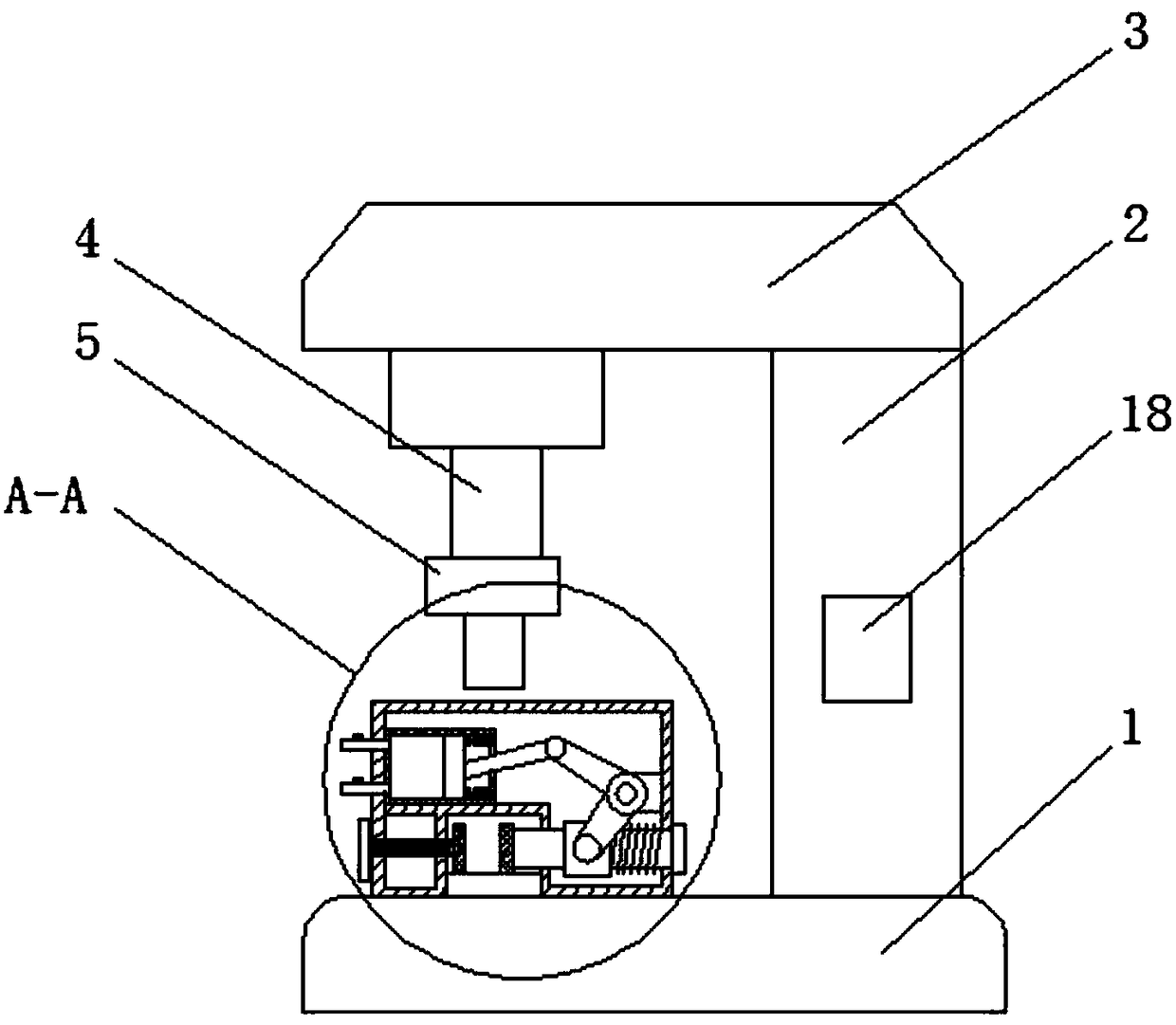
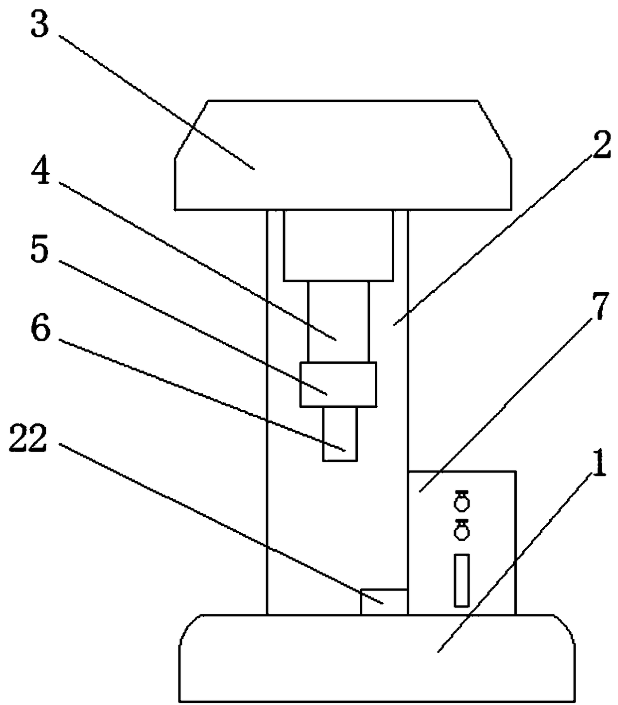
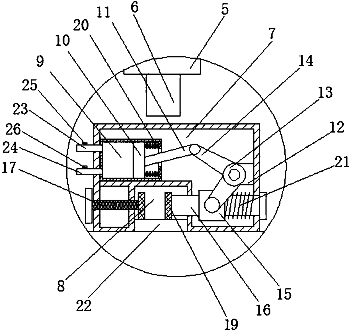
The invention discloses a rebar cutting-off device, and relates to the technical field of mechanical equipment. The rebar cutting-off device comprises a base, a supporting column is fixedly connectedto the right side of the top of the base, a top plate is fixedly connected to the top end of the supporting column, a hydraulic stretchable column is arranged at the position, located on the left sideof the supporting column, at the bottom of the top plate, a connecting block is fixedly connected to the bottom end of the hydraulic stretchable column, a cutting-off head is fixedly connected to thebottom of the connecting block, a clamp machine shell is fixedly connected to the position, located on the left side of the supporting column, of the top of the base, and a clamp groove is formed inthe bottom of the clamp machine shell. By means of the rebar cutting-off device, when cutting-off operation is carried out, a worker does not need to hold a rebar with the hand, uneven rebar cutting caused by manmade errors is avoided, the rebar cutting device has the automatic clamping function, the potential safety hazard that the worker is mistakenly injured during operation is avoided, labor intensity of the worker is reduced, and the working efficiency is improved.

Description

technical field [0001] The invention belongs to the technical field of mechanical equipment, in particular to a steel bar cutting device. Background technique [0002] A steel bar cutter is a tool used to cut steel bars. Generally, there are fully automatic steel bar cutting machines and semi-automatic steel bar cutting machines. It is one of the necessary equipment for steel bar processing, and it is mainly used for cutting steel bars to fixed length in housing construction, bridges, tunnels, power stations, large-scale water conservancy and other projects. Compared with other cutting equipment, the steel bar cutting machine has the characteristics of light weight, low energy consumption, reliable operation and high efficiency. Therefore, it has been widely used in mechanical processing and small rolling mills in recent years, and has played an important role in various fields of national economic construction. role. [0003] At present, the traditional steel bar cutting...

Claims


Application Information

Patent Timeline
Patent Type & Authority Applications(China)
IPC IPC(8): B21F11/00
CPCB21F11/00
Inventor 罗丙伍
Owner 合肥市硕理机电科技有限公司
Learn More