Manual clamping structure

A technology of clamping structure and handle, which is applied in the field of manual clamping structure, can solve the problems of damaged jaws and damaged parts, and achieve the effects of reducing production costs, facilitating production and assembly, and reducing surface damage

Inactive Publication Date: 2018-07-27
苏州鸣人金属制品有限公司
View PDF0 Cites 2 Cited by
  • Summary
  • Abstract
  • Description
  • Claims
  • Application Information

AI Technical Summary

Problems solved by technology

[0002] The chuck of the traditional mechanical gripper is rigidly connected with the mechanical arm. During the flow operation, the spatial position of the gripper gripping the part is preset. When two or more parts are stacked in the gripping position of the part, the part will The longitudinal height of the robot arm will be greater than the pre-set pick-up height of the part, and the gripper part of the mechanical gripper will hit the part. Due to the large inertial force during the operation of the robot arm, the part will be damaged, and the gripper will be damaged at the same time.

Method used


Image

  • Manual clamping structure
  • Manual clamping structure

Examples


Embodiment Construction

[0010] The preferred embodiments of the present invention will be described in detail below in conjunction with the accompanying drawings, so that the advantages and features of the present invention can be more easily understood by those skilled in the art, so as to make a clearer and clearer definition of the protection scope of the present invention.

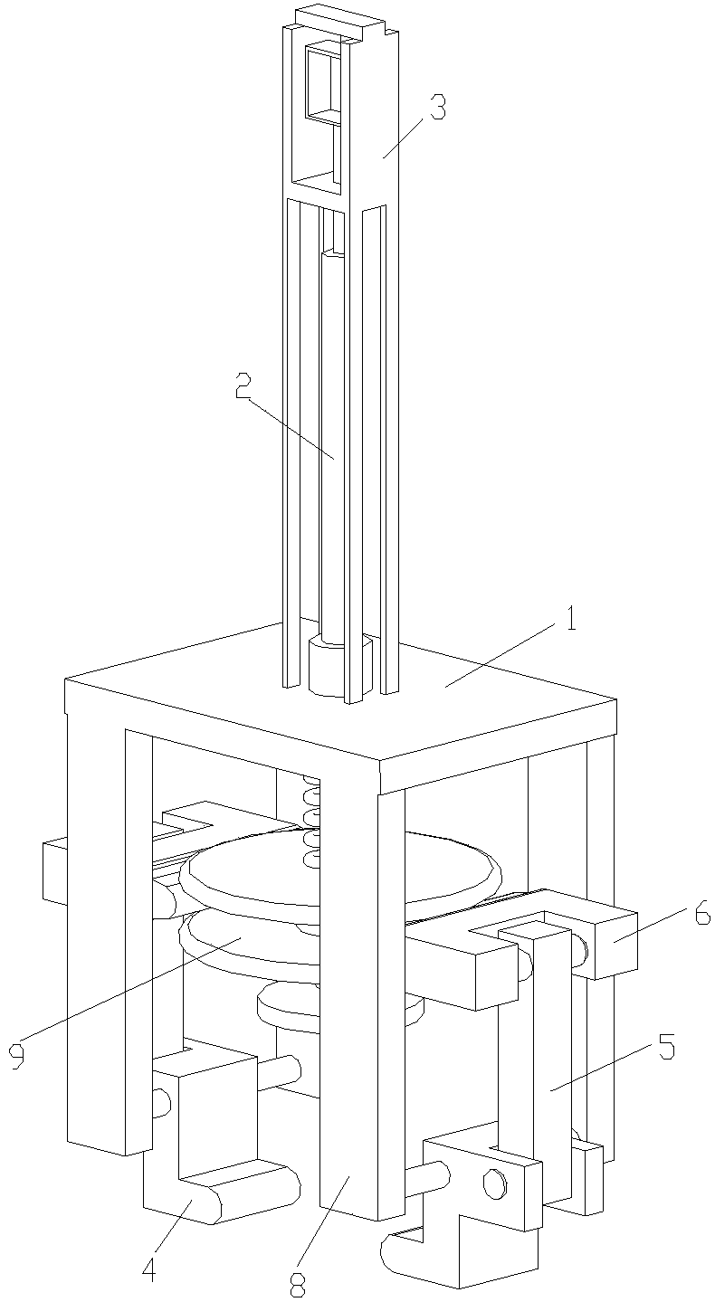
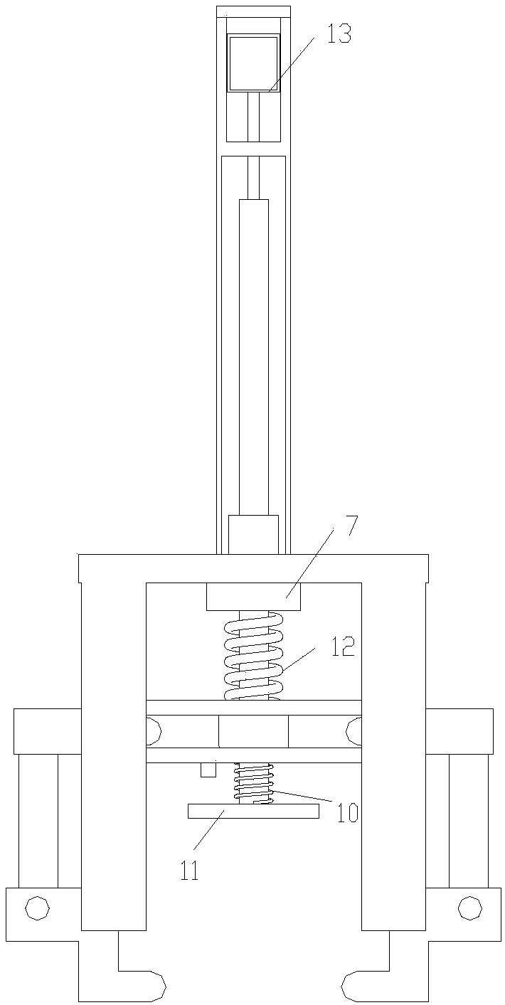
[0011] See attached figure 1 with 2 , The embodiment of the present invention includes:

[0012] A manual clamping structure includes a bottom plate 1, a guide rod 2, a handle 3, a claw head 4, a connecting rod 5 and a transmission block 6. The bottom plate 1 is provided with a guide sleeve 7 which is matched with the guide rod 2, and the guide rod 2 is sleeved in the guide sleeve 7, and the sliding fit can drive with lower friction and reduce energy consumption. The claw head 4 is fixed on the lower surface of the bottom plate 1 by a support column 8, and the two claw heads 4 are arranged oppositely. The claw head 4 has a Z-shap...


PUM


Abstract

The invention provides a manual clamping structure. A bottom plate is provided with a guide sleeve matched with a guide rod, the lower surface of the bottom plate is fixedly provided with claw heads through supporting pillars, and folding corners on the claw heads are fixed to the supporting pillars on the two sides of the claw heads through rotating shafts. The two claw heads oppositely arrangedclamp workpieces through clamping ends rotating in the opposite directions, and connection ends are hinged to transmission blocks through connection rods. The transmission blocks are matched with a transmission head at the lower end of the guide rod. The rotative surface of the transmission head is provided with grooves matched with the transmission blocks, one ends of the transmission blocks areprovided with protrusions, the protrusions are inserted into the grooves, and the transmission head rotates with the protrusions in the grooves as the axes. The lower end face of the transmission headis further provided with a limiting plate supported by a first spring. The guide rod is further provided with a second spring, and the second spring is arranged between the transmission head and thebottom plate in a supported manner. The upper end of the guide rod is provided with a hand shank. The hand shank comprises an outer frame arranged on the upper end face of the bottom plate in a supported manner, and the upper end face of the guide rod is provided with a handle to be held. The handle is lifted opposite to the outer frame, and the guide rod slides along the guide sleeve in an oppositely stretching and contracting manner.

Description

Technical field [0001] The invention relates to the field of mechanical hardware structures, in particular to a manual clamping structure. Background technique [0002] The chuck of the traditional mechanical gripper is rigidly connected with the mechanical arm. During the flow operation, the spatial position of the gripping part of the gripper is preset. When two or more parts are stacked in the part clamping position, the parts The longitudinal height of the robot arm will be greater than the part picking height preset by the manipulator, and the gripper part of the mechanical gripper will hit the part. Due to the large inertia force during the operation of the manipulator, it will damage the part and the gripper. Summary of the invention [0003] A technical solution adopted by the present invention is to provide a manual clamping structure, which includes a bottom plate, a guide rod, a handle, a claw head, a connecting rod, and a transmission block; the bottom plate is provide...

Claims


Application Information

Patent Timeline
Patent Type & Authority Applications(China)
IPC IPC(8): B25J15/10B25J19/00
CPCB25J15/10B25J19/00B25J19/0075
Inventor 陈桂琴
Owner 苏州鸣人金属制品有限公司
Why Eureka
Try Eureka