
Pneumatic power assisting device adopting tandem gas tanks

A technology of a booster device and a gas tank, which is applied in non-mechanical gear transmission devices, transportation and packaging, vehicle gearboxes, etc., can solve the problem that the energy collection efficiency cannot be adjusted in real time, etc., to achieve the energy collection efficiency is convenient, easy to adjust, and prevent loss. The effect of power

Active Publication Date: 2018-07-27
ANHUI UNIVERSITY OF TECHNOLOGY AND SCIENCE
View PDF13 Cites 0 Cited by
  • Summary
  • Abstract
  • Description
  • Claims
  • Application Information

AI Technical Summary

Problems solved by technology

[0006] The purpose of the present invention is to solve the problem that the energy collection efficiency of pneumatic mopeds cannot be adjusted in real time in the prior art, and to provide a pneumatic power booster using series gas tanks, which can adjust the compression ratio by connecting the energy storage gas tanks and energy supply gas tanks in series The compression cylinder compresses air into the energy storage gas tank, so that the energy collection efficiency of the pneumatic moped can be adjusted easily without affecting the normal use of the energy supply gas tank

Method used


Image

  • Pneumatic power assisting device adopting tandem gas tanks
  • Pneumatic power assisting device adopting tandem gas tanks

Examples


Embodiment 1

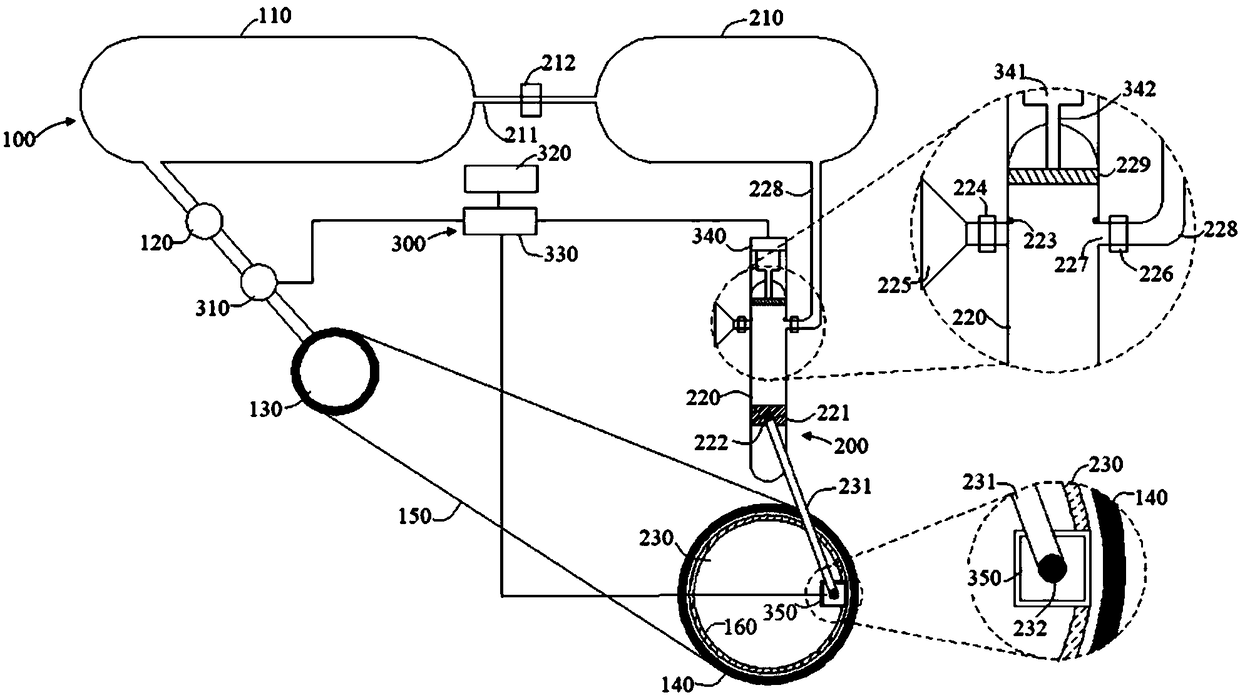
[0035] Refer to attached figure 1 and figure 2 As shown, a pneumatic booster device using series gas tanks in this embodiment includes a booster unit 100, a power recovery unit 200, and a control unit 300. The control unit 300 is used to regulate the booster unit 100 and the power recovery unit 200. The unit 100 includes an energy supply gas tank 110, an air motor 130 and a power wheel 140. The energy supply gas tank 110 is connected to the air motor 130 through a pipeline, and the air motor 130 is connected to the power wheel 140 through a transmission chain 150. The energy supply gas tank 110 Sending high-pressure gas to the air motor 130 through the pipeline drives the air motor 130 to rotate. The air motor 130 rotates and drives the power wheel 140 to rotate at the same time. An on-off valve 120 is provided between the energy supply gas tank 110 and the air motor 130 . When the device needs to be boosted, the on-off valve 120 is opened, and the high-pressure gas in the e...

Embodiment 2

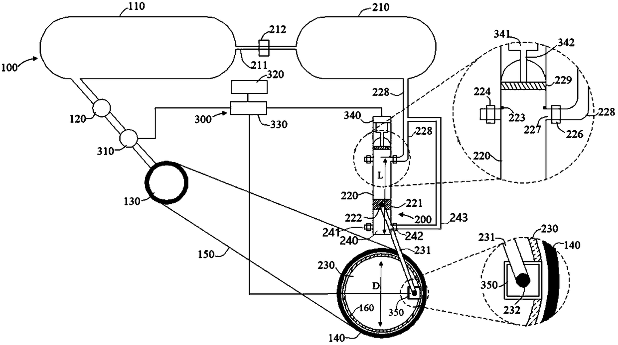
[0045] The basic structure of this embodiment is the same as that of Embodiment 1, the difference being that: the lower end of the compression cylinder 220 is provided with a second one-way inlet valve 241 and a second one-way outlet valve 242, and the second one-way outlet valve 242 The second air outlet pipe 243 communicates with the compression cylinder outlet pipe 228. The lower end of the compression cylinder 220 forms the second air chamber 240. The transmission rod 231 drives the compression piston 221 to move up and down in the compression cylinder 220. When the compression piston 221 wants to move up, The first one-way inlet valve 224 is closed due to the flow direction being blocked, and the first one-way outlet valve 226 is opened. At the same time, the second one-way inlet valve 241 in the second air cavity 240 is opened, and the second one-way outlet valve 242 is closed. The air in the compression cylinder 220 enters the air outlet pipe 228 of the compression cylin...


PUM


Abstract

The invention relates to a pneumatic power assisting device adopting tandem gas tanks, and belongs to the technical field of pneumatic equipment. The pneumatic power assisting device comprises a powerassisting unit, a power recovery unit and a control unit. The control unit is used for controlling the working efficiency of both the power assisting unit and the power recovery unit. The control unit adjusts an adjusting piston of a compression cylinder by controlling a clearance adjusting mechanism, so that the compression ratio of the compression cylinder is adjusted. According to the pneumatic power assisting device adopting the tandem gas tanks, the energy collecting efficiency of a pneumatic power assisting vehicle can be adjusted conveniently, and normal use of the energy supply gas tank cannot be affected.

Description

technical field [0001] The invention belongs to the technical field of pneumatic equipment, and in particular relates to a pneumatic power booster using series-connected gas tanks. Background technique [0002] my country is the kingdom of bicycles, and bicycles are loved by people because of their environmental protection, lightness and safety. [1] . In order to meet the needs of the people for different functions of bicycles. In terms of function, there are many types of bicycles: recreational, competitive, and portable. The appearance of the bicycle is even more varied. Bicycle has always been one of the means of transportation most closely related to people's daily life. Although in today's highly developed science and technology, there are many means of transportation that are more comfortable, faster and more convenient than bicycles, such self-centered means of transportation like bicycles are becoming more and more popular and have become an important part of urb...

Claims


Application Information

Patent Timeline
Patent Type & Authority Applications(China)
IPC IPC(8): B62M19/00
CPCB62M19/00Y02E60/16
Inventor 徐振法王银凤梁利东谢正好
Owner ANHUI UNIVERSITY OF TECHNOLOGY AND SCIENCE
Learn More