Powder storage bin fluidization device capable of being cleaned online

A storage bin and fluidizer technology, applied in the field of powder or granular conveying devices, can solve the problems of loss of elasticity, inability to seal the inner wall of the bin, complicated installation and replacement, etc., and achieve the effect of long service life

Pending Publication Date: 2018-07-27
上海威泽尔机械设备制造有限公司
View PDF0 Cites 0 Cited by
  • Summary
  • Abstract
  • Description
  • Claims
  • Application Information

AI Technical Summary

Problems solved by technology

[0003] a. The diaphragm of the fluidizer is easy to age and lose its elasticity, and cannot be sealed and the gap between the inner wall of the

Method used


Image

  • Powder storage bin fluidization device capable of being cleaned online
  • Powder storage bin fluidization device capable of being cleaned online

Examples


Embodiment Construction

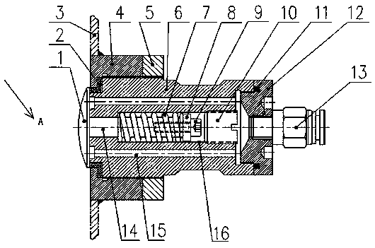
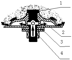
[0016] Please refer to the attached figure 1 As shown, the present invention is to fix an air valve on the storage bin wall 3, including a valve body 6 and a valve core. The valve core is made of a valve shaft 14 and a valve core cap 1. One end is filled with pressure gas, and the valve core cap 1 is affected by the pressure gas and leaves the storage bin wall 3. At the same time, the pressure gas is sprayed into the storage bin to break up the agglomerated and bridging materials; to remove the pressure gas, the spring 7 makes The valve shaft 14 shrinks inwardly, and the valve core cap 1 covers the jet nozzle of the valve body again.

[0017] One end of the valve shaft 14 is connected to the valve core cap 1, and the other end is screwed to the screw 9 through a washer 8. The right end of the screw 9 has a plug 10 screwed on the internal thread of the inner wall of the valve body 6, and the right end of the valve body 6 is connected with an end cap. 12 are screwed, and the e...


PUM


Abstract

The invention provides a powder storage bin fluidization device capable of being cleaned online. According to the technical scheme, an air valve is fixed on the wall of a storage bin, and comprises avalve body and a valve element, wherein the valve element is composed of a valve shaft and a valve element cap; a spring sleeves the valve shaft, one end of the valve body is filled with pressure gas,the valve element cap is away from the wall of the storage bin under the action of the pressure gas, and meanwhile, the pressure gas is injected into the storage bin to scatter caked and bridged materials; and the pressure gas is removed, the spring enables the valve shaft to contract inwards, and the valve element cap covers an air injection nozzle of the valve body again. The powder storage binfluidization device has the advantages of being capable of achieving cleaning online, long in service life and safe and reliable.

Description

technical field [0001] The invention relates to a powder or granule conveying device in the chemical, pharmaceutical and food industries, in particular to a bridge-breaking device that can be cleaned online. Background technique [0002] When powders or granules of different properties are temporarily stored or stored in the storage bin, wall hanging and bridging may occur. As an effective bridge-breaking device, the fluidizer is a flow-aiding component in the process of powder discharge from the warehouse. It is installed in the lower part of the hopper, see attached figure 2 A schematic diagram of an existing fluidizer is shown. The compressed air enters the inner side of the bin body through the central hole of the air injection plug 1, pushes the fluidizer diaphragm 2 to open, and the air flow is ejected from the opening gap of the fluidizer diaphragm, and the surrounding materials are blown up to achieve the powder flow. state and unload smoothly, avoiding bridging p...

Claims


Application Information

Patent Timeline
IPC IPC(8): B65D88/72
CPCB65D88/72
Inventor 俞建宏
Owner 上海威泽尔机械设备制造有限公司
Why Eureka
Try Eureka