Water discharge kerb and road

A technology of curb and body, applied in the field of drainage curb and roads including the drainage curb, can solve the problems of affecting drainage efficiency, difficult collection and cleaning of dirt, and many impurities, so as to ensure smooth drainage and improve drainage. Efficiency, the effect of reducing the frequency of cleaning

Pending Publication Date: 2018-07-27
CHINA CITY ENVIRONMENT PROTECTION ENGINEERING LIMITED COMPANY
View PDF5 Cites 4 Cited by
  • Summary
  • Abstract
  • Description
  • Claims
  • Application Information

AI Technical Summary

Problems solved by technology

Although this setting method is simple and easy to implement, its disadvantages are also obvious: the internal roads of iron and steel enterprises have large dust, many impurities, and heavy oil pollution in some areas. After the drainage pipe network in the factory area, it will affect the stability of the drainage pipe network, and it will be easily blocked, which will affect the drainage efficiency

Method used


Image

  • Water discharge kerb and road
  • Water discharge kerb and road
  • Water discharge kerb and road

Examples


Embodiment 1

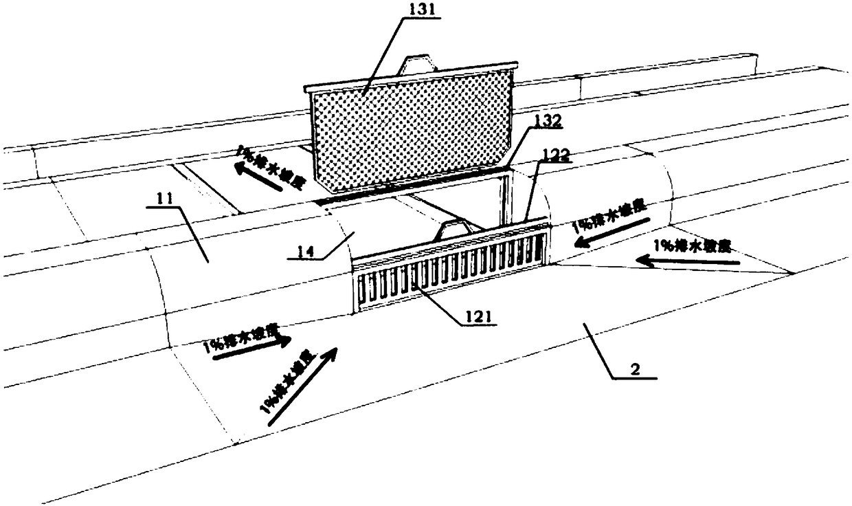
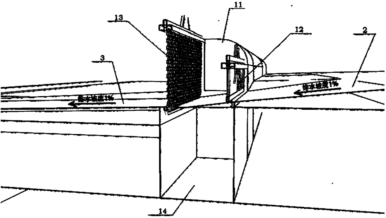
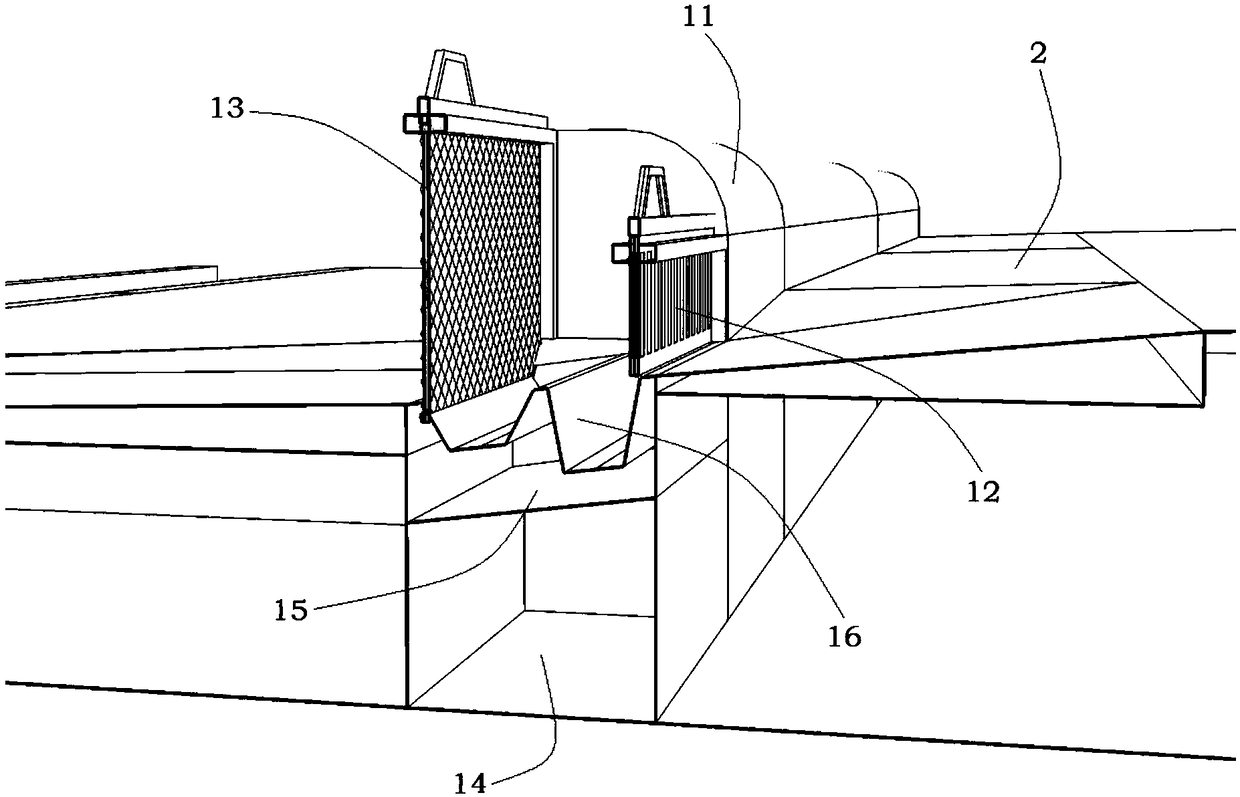
[0022] Such as figure 1 and figure 2 , the embodiment of the present invention provides a drainage curb, including a curb body 11, the curb body 11 is formed with a wall extending from the side wall of the road surface to the other side (ie, the side away from the road surface 2) The drainage channel is provided with a coarse filter unit 12 and a fine filter unit 13 in sequence along the drainage direction, and an overflow buffer channel 14 is formed between the coarse filter unit 12 and the fine filter unit 13 . Wherein, preferably, the above-mentioned coarse filter unit 12 is installed on the side wall of the road surface of the curb body 11, and the fine filter unit 13 is installed on the other side wall of the curb body 11, between the two There is a relatively long overflow buffer channel 14, which is convenient for the sedimentation and collection of dirt, and the filtrate filtered by the fine filter unit 13 is temporarily stored in the overflow buffer channel 14, whic...

Embodiment 2

[0034] Such as Figure 1-Figure 3 , the embodiment of the present invention relates to a road, including a roadbed 2, at least one side of the roadbed 2 is provided with a divider, and the divider includes a plurality of curbstones connected in series along the length direction of the road surface, at least one of which is the roadbed The curbstone is the drainage curbstone provided in the first embodiment above, and the specific structure of the drainage curbstone will not be repeated this time.

[0035] Preferably, as Figure 1-Figure 3 The road surface 2 near the drainage curb has a certain slope, preferably no less than 1%, in order to divert the accumulated water on the road surface 2 to the drainage curb. Preferably, drainage slopes are provided along the length direction of the road surface and the width direction of the road surface, so as to form a low-lying area converging toward the coarse filter unit 12 .

[0036] Further, a section of drainage ramp 3 is provided...


PUM


Abstract

The invention relates to a water discharge kerb and a road comprising the water discharge kerb. The water discharge kerb comprises a kerb body, wherein a water discharge passage extending to the otherside wall body from the side wall body of the pavement is formed on the kerb body; a coarse filtering unit and a fine filtering unit are sequentially arranged on the water discharge passage in the water discharge direction; a flow passing buffer groove passage is defined between the coarse filtering unit and the fine filtering unit; through the matching of the coarse filtering unit, the flow passing buffer groove passage and the fine filtering unit, the dirt interception capability of the kerb can be effectively improved; when the kerb is applied to enterprise inside roads in iron and steel industries and the like, the proportion of sludge, sundries, oil stain and the like entering a factory water discharge system can be reduced; the cleaning frequency of the water discharge system can beeffectively reduced; the water discharge efficiency is improved; the water discharge smoothness in the factory can be ensured.

Description

technical field [0001] The invention relates to a drainage curb stone and a road including the drainage curb stone, in particular to a drainage curb stone which can be used for road drainage of iron and steel enterprises. Background technique [0002] Existing iron and steel enterprises basically do not set drainage curbstones inside. When encountering parts that need to be connected with drainage ditches or drainage pipe networks, they often adopt the form of not setting curbstones and leaving a gap for drainage. Although this setting method is simple and easy to implement, its disadvantages are also obvious: the internal roads of iron and steel enterprises have large dust, many impurities, and heavy oil pollution in some areas. After the drainage pipe network in the factory area, it will affect the stability of the drainage pipe network, and it will be easily blocked, which will affect the drainage efficiency. Contents of the invention [0003] The embodiments of the pr...

Claims


Application Information

Patent Timeline
Patent Type & Authority Applications(China)
IPC IPC(8): E01C11/22E03F5/14E03F5/16
CPCE01C11/223E03F5/14E03F5/16Y02A10/30
Inventor 姚远孙勇刘昊坤
Owner CHINA CITY ENVIRONMENT PROTECTION ENGINEERING LIMITED COMPANY
Why Eureka
Try Eureka