Automobile gear-engaging sliding fuel saving device

A technology of belt and fuel saving in automobiles, applied in the field of auto parts, can solve problems such as easily damaged gearboxes, loss of engine braking effect, incomplete fuel combustion, etc., to prolong the sliding process with gears, reduce braking effects, and save fuel effect of effect

Inactive Publication Date: 2018-07-27
WEIFANG UNIVERSITY
View PDF4 Cites 12 Cited by
  • Summary
  • Abstract
  • Description
  • Claims
  • Application Information

AI Technical Summary

Problems solved by technology

[0004] In order to avoid the speed drop too fast and extend the sliding distance as much as possible, many car drivers will use the method of sliding in neutral gear, but there are many hidden dangers in sliding in neutral gear
First of all, coasting in neutral cuts off the power connection between the engine and the wheels, and loses the braking effect of the engine. Compared with a higher speed per hour, when encountering an emergency brake, the braking distance will be significantly extended, which can easily lead to collision accidents. ;Secondly, coasting in neutral cuts off the power connection between the engine and the wheels, and the engine is no longer driven by the wheels to rotate, but instead enters the state of idling fuel injection, and the fuel is prone to incomplete combustion, which will cause exhaust pollution and carbon deposits, etc.; finally, for For automatic cars, sliding in neutral can easily damage the gearbox

Method used


Image

  • Automobile gear-engaging sliding fuel saving device
  • Automobile gear-engaging sliding fuel saving device
  • Automobile gear-engaging sliding fuel saving device

Examples


Embodiment 1

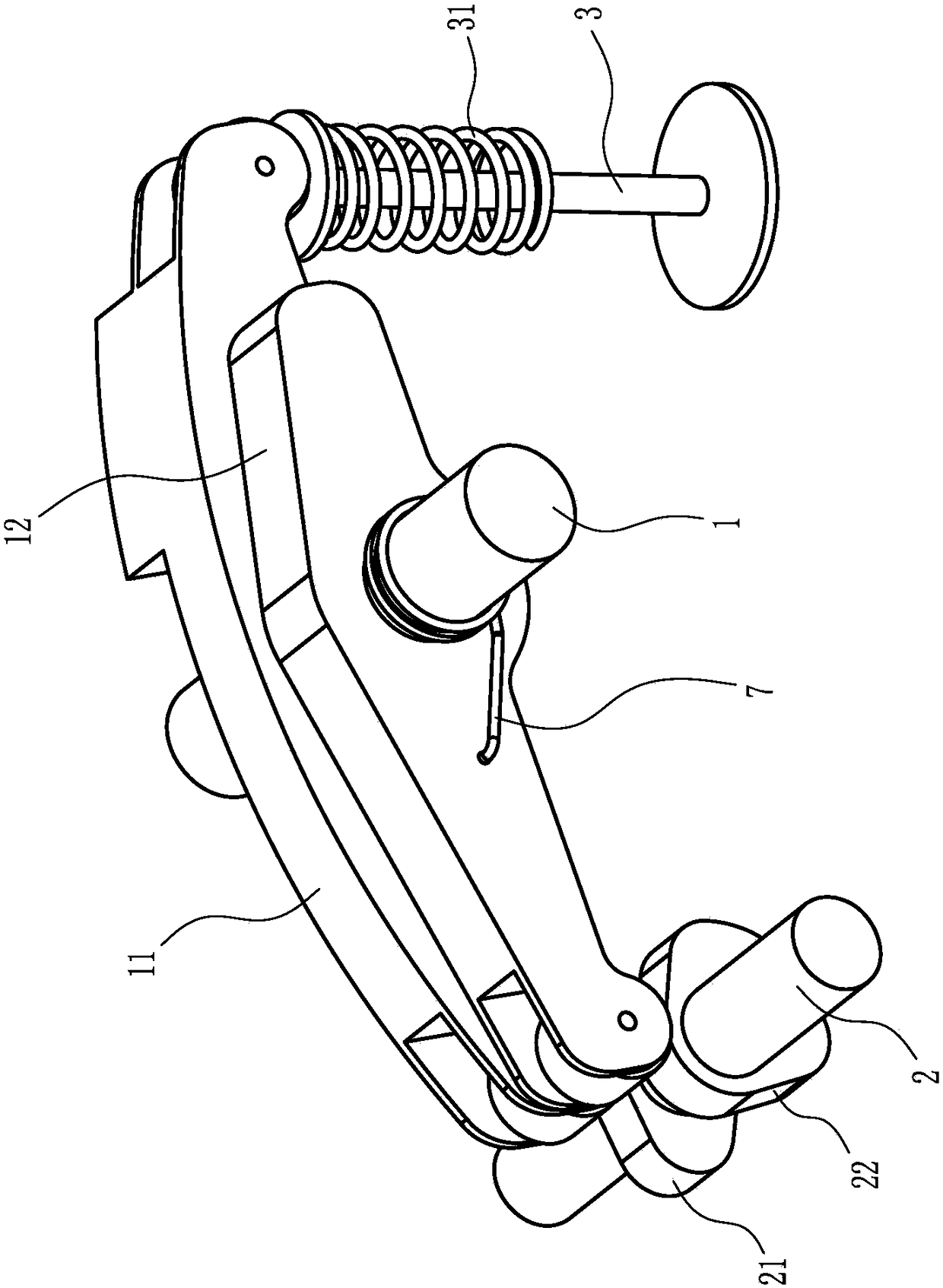
[0024] Embodiment one: if figure 1 and figure 2 As shown, the automobile sliding fuel-saving device with gears includes a rocker shaft 1 and a camshaft 2 installed on the engine. One end of the main rocker arm 11 corresponds to the main cam 21, and the other end of the main rocker arm 11 abuts against the intake valve 3 or the exhaust valve. The above-mentioned structure is a conventional structure of an existing engine. Of course, the intake valve A valve return spring 31 is also provided on the door 3 or the exhaust valve.

[0025] To facilitate the description of the principle of this embodiment, the following description takes the intake valve 3 as an example.

[0026] The four strokes of a four-stroke engine are respectively an intake stroke, a compression stroke, a power stroke, and an exhaust stroke, wherein the intake valve 3 is opened during the intake stroke, and the opening of the intake valve 3 is caused by the valve on the camshaft 2. The main cam 21 pushes on...

Embodiment 2

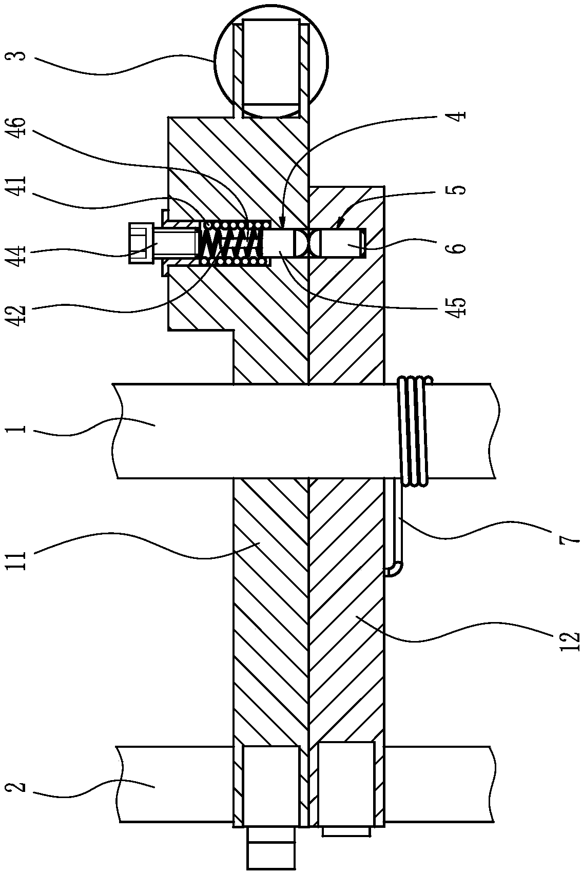
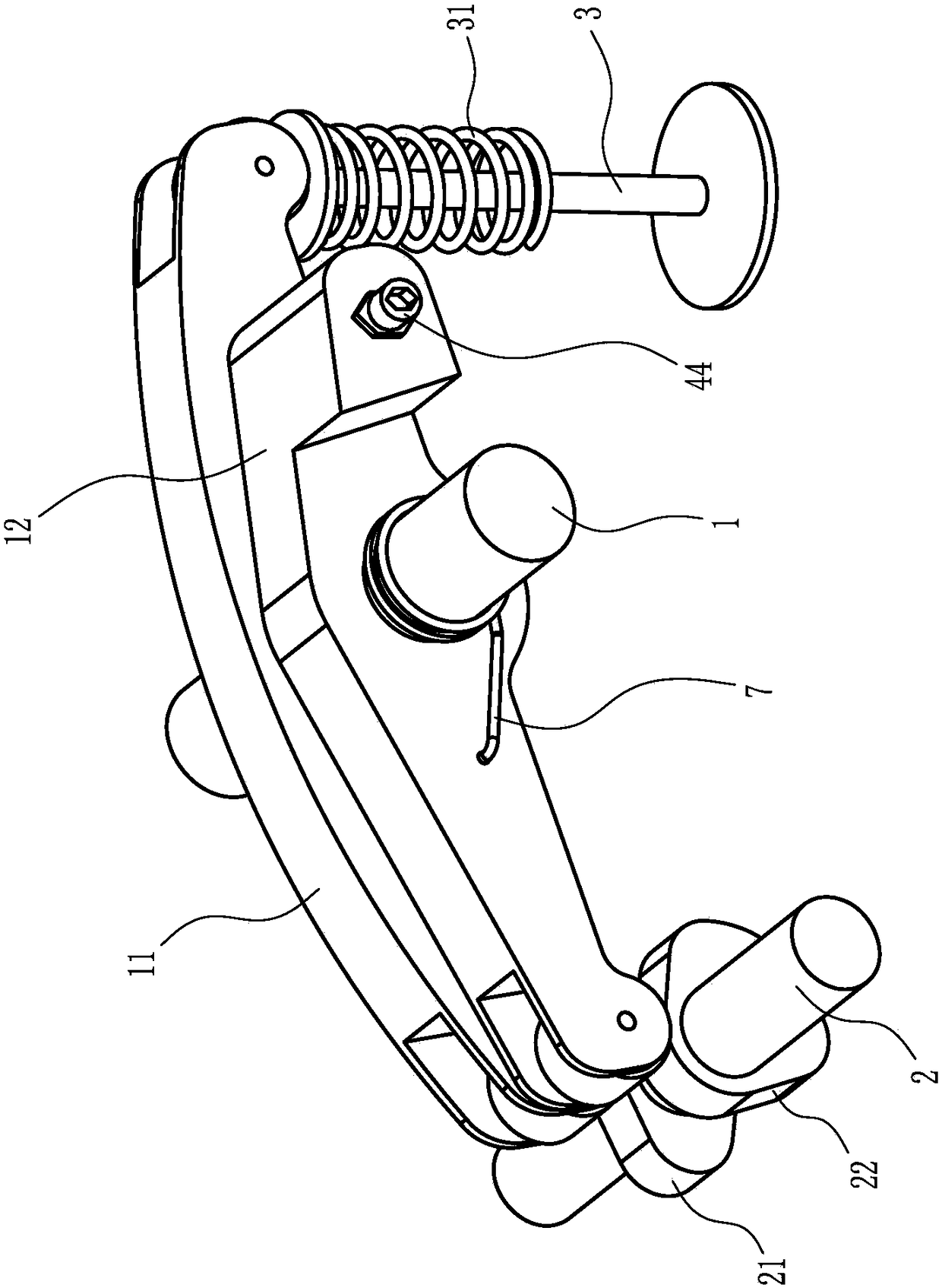
[0035] Embodiment two: if image 3 and Figure 4 As shown, the difference between this embodiment and Embodiment 1 is that: the connecting pin hole 5 is set on the main rocker arm 11, the continuous break control installation hole 4 is set on the auxiliary rocker arm 12, A magnetic connection pin 6 is slidably installed in the continuous control installation hole 4 . The anti-attraction force applying device includes a connecting pin protruding connecting spring 43 arranged in the continuous break control installation hole 4 and abutting against the end surface of the magnetic connecting pin 6 away from the main rocker arm 11 , the A spring abutment bolt 44 is threadedly mounted on the end of the continuous break control installation hole 4 away from the main rocker arm 11 , and the spring abutment bolt 44 in this embodiment can simultaneously adjust the preload of the connecting pin protruding from the connecting spring 43 force. The connecting pin breakage limiting device...


PUM


Abstract

The invention discloses an automobile gear-engaging sliding fuel saving device which comprises a rockshaft and a camshaft. A primary rocker arm and a secondary rocker arm are rotationally mounted on the rockshaft, and a primary cam and a secondary cam are arranged on the camshaft. The other end of the primary rocker arm abuts against an inlet valve or an exhaust valve, and a rocker arm connectingand disconnecting device is arranged between the primary rocker arm and the secondary rocker arm and has a sliding connecting state and a non-sliding disconnecting state. The rocker arm connecting anddisconnecting device is connected with an automobile electric control unit, and a protruding part of the secondary cam jacks the secondary rocker arm in an engine compression stroke and power stroke.According to the automobile gear-engaging sliding fuel saving device, when an automobile enters in a gear-engaging sliding state, the secondary cam can drive the primary rocker arm to act in the engine compression stroke to enable the primary rocker arm to open the inlet valve or the exhaust valve, resistance in the engine compression stroke is greatly reduced, the gear-engaging sliding process is effectively prolonged, and the good fuel saving effect is achieved; and an engine still keeps in power connection with wheels, the braking state of the engine can be restored at any time, and the driving safety is improved.

Description

technical field [0001] The invention relates to the technical field of automobile parts, in particular to an automobile sliding fuel-saving device with gears. Background technique [0002] Most automobile engines now use electronic fuel injection systems, and the ECU (automotive electronic control unit) controls the fuel injection volume. After reaching a relatively high speed in the same gear, release the accelerator pedal, and the ECU will control the engine speed according to the detected engine speed and current speed. The fuel injector stops injecting fuel, and the engine is driven by the car to rotate at this time, that is, the car enters the sliding state with gears. When the speed of the car drops, the engine speed drops accordingly. When the engine speed drops to a certain value or when the driver refuels, the ECU controls the fuel injector to re-inject fuel, and then the engine drives the wheels to rotate. [0003] If the driver does not give fuel, the longer the ...

Claims


Application Information

Patent Timeline
Patent Type & Authority Applications(China)
IPC IPC(8): F01L1/18F02D13/02
CPCF01L1/18F01L1/181F02D13/02
Inventor 马成习王辉于志德
Owner WEIFANG UNIVERSITY
Why Eureka
Try Eureka