Screw pump reverse rotation preventing braking method

A screw pump, anti-reverse technology, applied in pump control, machine/engine, mechanical equipment, etc., can solve the problems of unreleased reverse energy, fast reverse speed, disintegration of pulleys, etc., to facilitate integrated installation, Increased braking force and reliable braking effect

Inactive Publication Date: 2018-07-27
DAQING SENENPU MACHINERY MFG
View PDF0 Cites 7 Cited by
  • Summary
  • Abstract
  • Description
  • Claims
  • Application Information

AI Technical Summary

Problems solved by technology

[0003] At present, the commonly used anti-reverse methods include ratchet and pawl type and electromagnetic brake type, both of which lock the ground transmission rod at the moment when the screw pump stops working, and the reverse energy cannot be released. , it is necessary to manually loosen the anti-reverse device to release the reverse energy, the process of energy release is uncontrollable, the reverse speed is very fast, and it is very easy to cause accidents caused by sucker rod bending or pulley disintegration; in addition, once In the event of an unexpected power failure, the electromagnetic brake anti-reverse method will fail

Method used


Image

  • Screw pump reverse rotation preventing braking method
  • Screw pump reverse rotation preventing braking method
  • Screw pump reverse rotation preventing braking method

Examples


Embodiment Construction

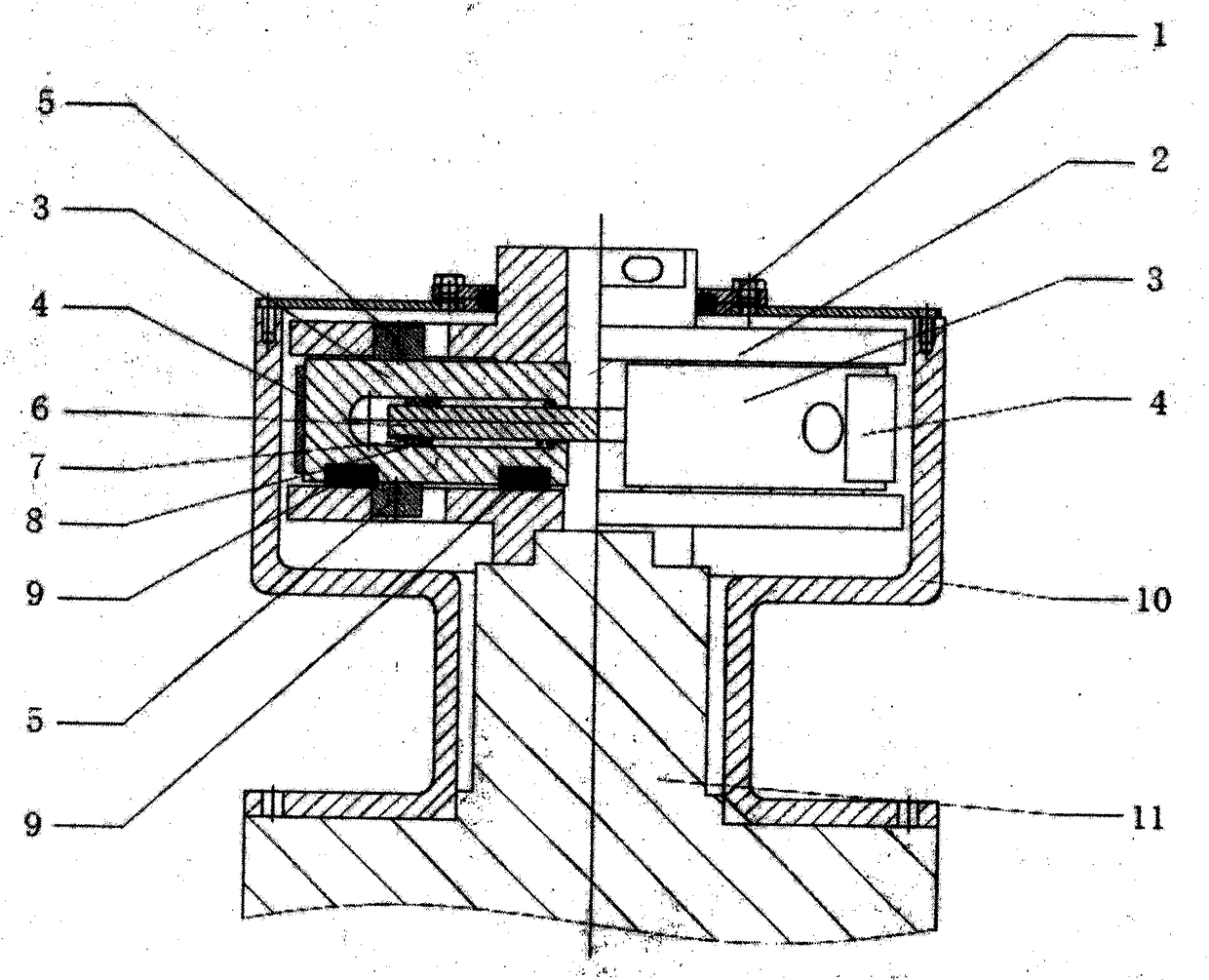
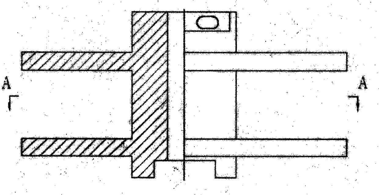
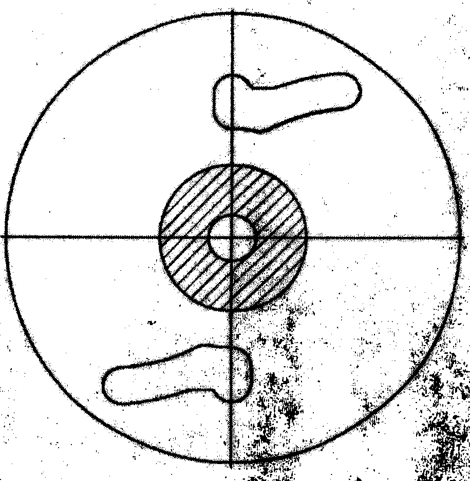
[0020] see figure 1 , this patent mainly consists of upper cover (1), centrifugal bracket (2), centrifugal block (3), brake pad (4), limit bolt (5), connecting bolt (6), round nut (7), spring ( 8), polytetrafluoro pad (9), outer casing (10) form.

[0021] Working process of the present invention is as follows:

[0022] When installing, respectively insert 2 brake pads (4) and 6 PTFE pads (9) into the corresponding positions of the two centrifugal blocks (3), then place the centrifugal support (2) horizontally, place the embedded brake The two centrifugal blocks (3) of the piece (4) and the polytetrafluoro pad (9) are placed between the upper and lower working surfaces of the centrifugal support (2), and then the four limit bolts (5) are respectively passed through the centrifugal support (2 ) are connected to the centrifugal block (3) to ensure that the centrifugal block (3) can only move along the track of the limit groove of the centrifugal support (2), and finally use the...


PUM


Abstract

The invention relates to a screw pump reverse rotation preventing braking method. An upper cover (1), a centrifugal support (2), centrifugal blocks (3), brake pads (4), limiting bolts (5), a connecting bolt (6), a circular nut (7), a spring (8), PTFE pads (9) and an outer shell (10) are included. A centrifugal braking system is composed of the centrifugal support (2), the centrifugal blocks (3), the brake pads (4), the limiting bolts (5), the connecting bolt (6), the circular nut (7), the spring (8) and the PTFE pads (9). During braking, the centrifugal blocks (3) are used for driving the brake pads (4) to rub with the inner wall of the outer shell (10) for braking. The centrifugal braking system can be arranged at the outer portion of a screw pump drive head together with the outer shell(10) and the upper cover (1) and can also be integrated into the screw pump drive head, a shell of the screw pump drive head serves as a friction face, and accordingly, the work effect of the centrifugal braking system is guaranteed.

Description

technical field [0001] The invention relates to an anti-reverse braking method of a screw pump. Background technique [0002] When the surface driving device of the oil production screw pump is in normal operation, the motor drives the sucker rod to rotate, which also drives the rotor of the downhole screw pump to rotate in the rubber stator to realize the lifting of the liquid. When the driving head stops running, the elastic energy accumulated in the sucker rod and the liquid column pressure due to the pressure difference of the liquid surface will be released through the sucker rod in the form of reverse rotation. Generally speaking, the ground drive head of the screw pump will have an anti-reverse device to control the release of this reverse energy. [0003] At present, the commonly used anti-reverse methods include ratchet and pawl type and electromagnetic brake type, both of which lock the ground transmission rod at the moment when the screw pump stops working, and t...

Claims


Application Information

Patent Timeline
Patent Type & Authority Applications(China)
IPC IPC(8): F04C14/06
CPCF04C14/06
Inventor 顾顺李学宏王立飞
Owner DAQING SENENPU MACHINERY MFG
Why Eureka
Try Eureka