Coil heat pipe

A heat pipe and coil technology, which is applied in indirect heat exchangers, lighting and heating equipment, etc., can solve the problems of uneven heat exchange and low heat exchange coefficient, so as to improve heat exchange effect, strengthen heat transfer, and improve heat exchange. The effect of efficiency

Active Publication Date: 2018-07-27
无锡市新五环节能科技有限公司
View PDF3 Cites 6 Cited by
  • Summary
  • Abstract
  • Description
  • Claims
  • Application Information

AI Technical Summary

Problems solved by technology

[0005] In view of the above problems, the present invention provides a new heat pipe, so as to solve the problems of low heat transfer coefficient and uneven heat transfer in the case of heat pipe heat exchange

Method used


Image

  • Coil heat pipe
  • Coil heat pipe
  • Coil heat pipe

Examples


Embodiment Construction

[0032] The specific embodiments of the present invention will be described in detail below in conjunction with the accompanying drawings.

[0033] In this article, if there is no special explanation, when it comes to formulas, " / " means division, and "×" and "*" mean multiplication.

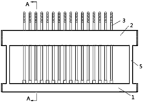
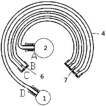
[0034] as attached figure 1 As shown, a heat pipe includes a lower header 1, an upper header 2, a coil 3 and a return pipe 5, the coil 3 communicates with the lower header 1 and the upper header 2, and the lower header 1 is the evaporation end, the condensation end includes at least a part of the upper header 2 and the coil 3, the fluid absorbs heat and evaporates in the lower header 1, and after exchanging heat with at least a part of the coil 3 and the upper header 2, Condensed in the upper header 2, the condensed fluid returns to the lower header 1 through the return pipe 5.

[0035] As preferably, there are one or more coiled pipes 3, for example, figure 1 A number of coils 3 are shown.

...


PUM


Abstract

The invention provides a heat pipe. The heat pipe comprises a lower collecting pipe, an upper collecting pipe, one or more coils and backflow pipes. The coils communicate with the lower collecting pipe and the upper collecting pipe. The lower collecting pipe serves as an evaporation end. A condensation end comprises the upper collecting pipe and at least one part of the coils. Fluid absorbs heat to evaporate in the lower collecting pipe; after heat exchanger is conducted between the at least one part of the coils and the upper collecting pipe, the fluid condenses in the upper collecting pipe;and the fluid obtained after condensation returns to the lower collecting pipe through the backflow pipes. Each coil comprises multiple arc-shaped heat exchange pipes. The ends of every two adjacent heat exchange pipes communicate with each other, so that the multiple heat exchange pipes form a series connection structure; and in addition, the end of each heat exchange pipe forms a heat exchange pipe free end. According to the novel heat pipe, the free ends are disturbed through volume expansion generated in the process that liquid changes into steam, and the problem that a heat pipe is low inheat exchange efficiency is solved.

Description

technical field [0001] The invention belongs to the field of heat pipes, in particular to a coil heat pipe. Background technique [0002] Heat pipe technology is a heat transfer element called "heat pipe" invented by George Grover of Los Alamos National Laboratory in the United States in 1963. It makes full use of the principle of heat conduction and phase change medium. The rapid heat transfer properties of the heat pipe quickly transfer the heat of the heating object to the heat source, and its thermal conductivity exceeds that of any known metal. [0003] Heat pipe technology was widely used in aerospace, military and other industries before. Since it was introduced into the radiator manufacturing industry, people have changed the traditional radiator design ideas and got rid of the single heat dissipation mode that only relies on high air volume motors to obtain better heat dissipation. The use of heat pipe technology enables the radiator to obtain a satisfactory heat e...

Claims


Application Information

Patent Timeline
Patent Type & Authority Applications(China)
IPC IPC(8): F28D15/02
CPCF28D15/025
Inventor 于仁麟
Owner 无锡市新五环节能科技有限公司
Why Eureka
Try Eureka