Communication system

A communication system and satellite communication system technology, applied in the transmission system, radio transmission system, satellite communication transmission, etc., can solve the problems of low network communication rate, performance limitation, and difficulty in downloading massive flight data, so as to reduce control and maintenance cost, increase the transmission rate, and the effect of fast data transmission

Pending Publication Date: 2018-07-27
宁波光舟通信技术有限公司
View PDF0 Cites 3 Cited by
  • Summary
  • Abstract
  • Description
  • Claims
  • Application Information

AI Technical Summary

Problems solved by technology

[0002] At present, the network communication of civil aviation aircraft during flight is mainly realized through the radio network transmission of satellites and ground base stations. This kind of implementation is limited by the radio frequency and the orbit position of geosynchronous satellites, and it is difficult to meet the rapid growth of mass data transmission in the civil aviation field. Requirements; and due to the performance limitation of the satellite radio communication network, the data transmission rate and the number of service users on the aircraft are limited. Although the Internet service in the cabin can be realized at present, the network communication rate is relatively low, basically in the order of KB and MB
[0003] Based on the above reasons, a large amount of flight data generated by the aircraft in the air cannot be transmitted to the ground in real time, making the aircraft an island of information in the air
With the development of aircraft intelligence, the data generated by intelligent aircraft equipped with thousands of sensors and complex digital systems has increased exponentially. If it is not effectively utilized, the control and maintenance costs of the aircraft cannot be reduced

Method used


Image

  • Communication system
  • Communication system
  • Communication system

Examples


Embodiment Construction

[0048] Exemplary embodiments of the present invention will be described in more detail below with reference to the accompanying drawings. Although exemplary embodiments of the present invention are shown in the drawings, it should be understood that the invention may be embodied in various forms and should not be limited to the embodiments set forth herein. Rather, these embodiments are provided for more thorough understanding of the present invention and to fully convey the scope of the present invention to those skilled in the art.

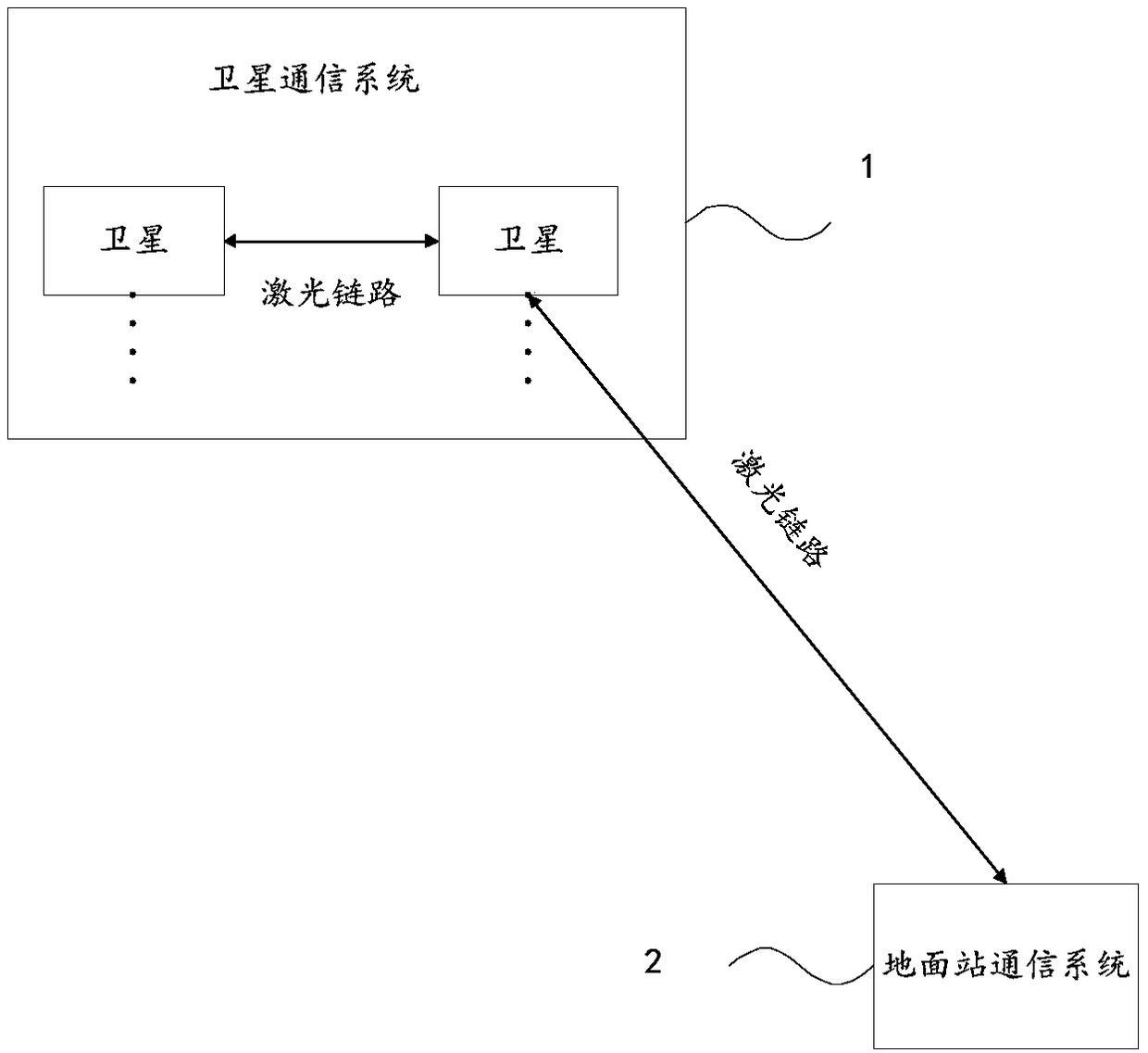
[0049] The present invention provides a communication system, such asfigure 1 As shown, it includes: a satellite communication system 1 and a ground station communication system 2 .

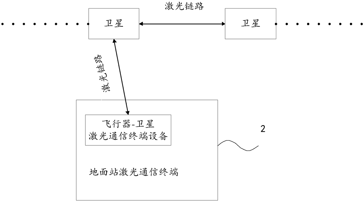
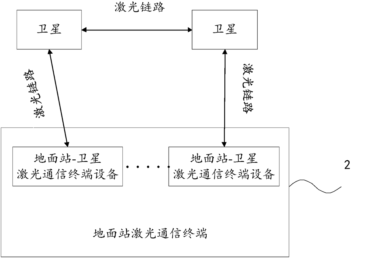
[0050] Satellite communication system 1, including a plurality of satellites, each satellite carries inter-satellite laser communication terminal equipment for inter-satellite communication, satellite-aircraft laser communication terminal equipment for communicatio...


PUM


Abstract

The invention discloses a communication system, relates to the technical field of aerospace, and mainly aims to increase the rate of data transmission in an aircraft network while the cost is reduced.The communication system comprises a satellite communication system and a ground station communication system, wherein the satellite communication system comprises multiple satellites; each satellitecarries an intersatellite laser communication terminal device for intersatellite communication, a satellite-aircraft laser communication terminal device for satellite-aircraft communication, and a satellite-ground station laser communication terminal device for satellite-ground station communication; communication between the multiple communication satellites is achieved through laser links basedon the intersatellite laser communication terminal device; the ground station communication system comprises a ground station laser communication terminal communicating with the satellites; the ground station laser communication terminal comprises a ground station-satellite laser communication terminal device, and communicates with the satellites through laser links based on the ground station-satellite laser communication terminal device. The communication system is mainly applied to data transmission of an aircraft.

Description

technical field [0001] The invention relates to the field of aerospace technology, in particular to a communication system. Background technique [0002] At present, the network communication of civil aviation aircraft during flight is mainly realized through the radio network transmission of satellites and ground base stations. This kind of implementation is limited by the radio frequency and the orbit position of geosynchronous satellites, and it is difficult to meet the rapid growth of mass data transmission in the civil aviation field. Requirements; and due to the performance limitation of the satellite radio communication network, the data transmission rate and the number of service users on the aircraft are limited. Although the Internet service in the cabin can be realized at present, the network communication rate is relatively low, basically in the order of KB and MB . [0003] Based on the above reasons, a large amount of flight data generated by the aircraft in t...

Claims


Application Information

Patent Timeline
Patent Type & Authority Applications(China)
IPC IPC(8): H04B7/185H04B10/118
CPCH04B7/18506H04B7/18508H04B7/1851H04B7/18517H04B7/18521H04B10/118
Inventor 潘运滨汪逸群刘军
Owner 宁波光舟通信技术有限公司
Why Eureka
Try Eureka