
Generation device for fluid shear stress and generation method of fluid shear stress

A technology of fluid shear force and generation device, which is applied in measurement devices, fluid controllers, chemical instruments and methods, etc., can solve the problems of inability to dynamically adjust the magnitude and ratio of fluid shear force, and inability to simulate the magnitude of fluid shear force. , to achieve the effect of easy promotion, simple structure, and extended ratio range

Active Publication Date: 2018-07-31
HARBIN INST OF TECH SHENZHEN GRADUATE SCHOOL
View PDF6 Cites 1 Cited by
  • Summary
  • Abstract
  • Description
  • Claims
  • Application Information

AI Technical Summary

Problems solved by technology

[0009] In order to overcome the deficiencies of the prior art, the present invention proposes a fluid shear force generating device and a fluid shear force generating method, which are used to solve the problem that the existing shear force generating device 1) cannot simulate the fluid shear force inside all blood vessels of the human body and 2) the problem that it is impossible to dynamically adjust the size and ratio of the fluid shear force in each flow channel without changing the input fluid velocity

Method used


Image

  • Generation device for fluid shear stress and generation method of fluid shear stress
  • Generation device for fluid shear stress and generation method of fluid shear stress
  • Generation device for fluid shear stress and generation method of fluid shear stress

Examples


Embodiment Construction

[0037] In the following, the concept, specific structure and technical effects of the present invention will be clearly and completely described in conjunction with the embodiments and the drawings, so as to fully understand the objectives, solutions and effects of the present invention. It should be noted that the embodiments in this application and the features in the embodiments can be combined with each other if there is no conflict.

[0038] It should be noted that, unless otherwise specified, when a feature is called "fixed" or "connected" to another feature, it can be directly fixed and connected to another feature, or indirectly fixed or connected to another feature. One feature. In addition, the descriptions of up, down, left, right, front, and back used in the present invention are only relative to the mutual positional relationship of the components of the present invention in the drawings.

[0039] In addition, unless otherwise defined, all technical and scientific ter...


PUM


Abstract

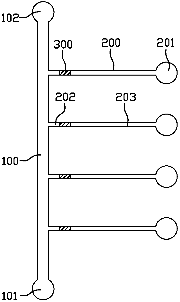
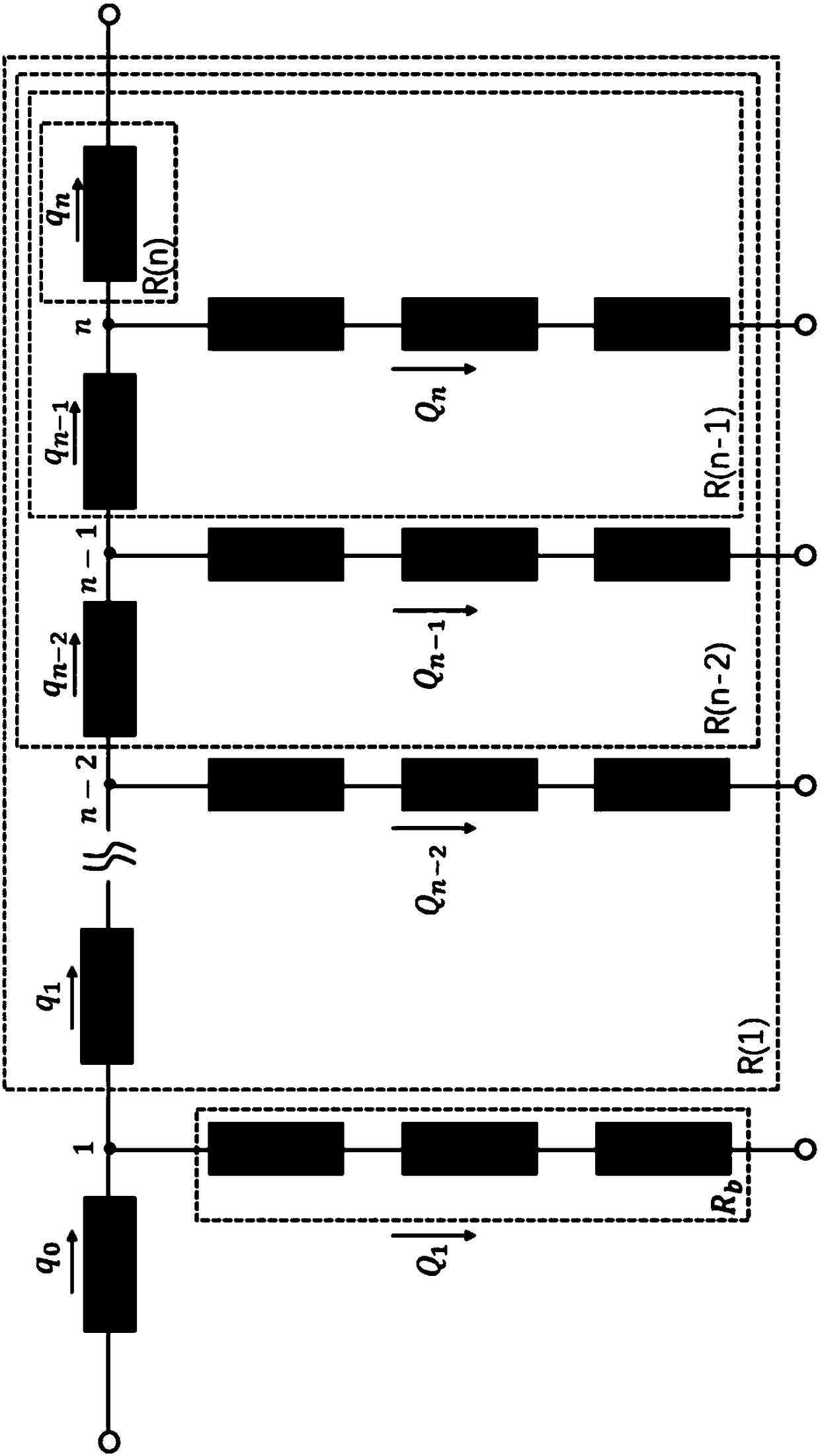
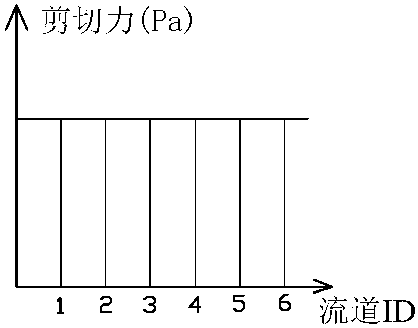
The invention relates to the field of microfluidic chips. The invention discloses a generation device for fluid shear stress and a generation method of the fluid shear stress. The device comprises a device main body, wherein the device main body is provided with a main flow passage and at least two branch flow passages; two ends of the main flow passage are provided with a fluid inlet and a main-flow-passage fluid outlet; certain ends of the branch flow passages are communicated with the main flow passage; the other ends of the branch flow passages are provided with branch-flow-passage fluid outlets; valves capable of regulating cross sectional area, which fluid can pass through, in the branch flow passages are arranged in the branch flow passages. The device, by utilizing the cooperationof the main flow passage, the branch flow passages and the valves, can be used for realizing the dynamic changes of the intensity and specific value of the fluid shear stress in the conditions that the flow velocity of the input fluid and the structure of the device are not altered. Meanwhile, the device can be used for greatly expanding the range of the specific value of the fluid shear stress infirst and final branch flow passages; moreover, the specific value of any point in the range can be covered, and the device is simple in structure, and is easy to popularize and realize.

Description

Technical field [0001] The invention relates to the field of microfluidic chips, in particular to a fluid shear force generating device that can realize a large range and dynamic adjustment of fluid shear force in a flow channel, and a fluid shear force generating method. Background technique [0002] The human body has a complex vascular system, ranging in diameter from a few microns to a few centimeters. The fluid shear force formed by blood flow in veins and arteries is about 0.7-9 dyn / cm, respectively 2 And 20-70dyn / cm 2 . In narrow arteries, the shear force sometimes exceeds 450 dyn / cm 2 . The shear force of blood flow is closely related to a series of complex biological processes in the human body. Simulating this complex shear environment in an in vitro model is of great significance to the study of endothelial cell function, cardiovascular disease and thrombus. [0003] As early as the 1980s, the parallel plate flow chamber and cone-plate viscometer shear force device we...

Claims


Application Information

Patent Timeline
IPC IPC(8): B01L3/00
CPCB01L3/5027B01L3/50273B01L3/502738B01L3/502746B01L3/502776B01L2300/0864B01L2400/0655B01L2400/082G01N33/4915
Inventor 陈华英
Owner HARBIN INST OF TECH SHENZHEN GRADUATE SCHOOL
Learn More