Iron remover with magnetic bar capable of being mounted fast

A technology of iron remover and magnetic rod, which is applied in the fields of magnetic separation, chemical instruments and methods, solid separation, etc., can solve the problems of ineffective removal of iron powder, deterioration of the quality of ultrafine powder, time-consuming and labor-intensive, and convenient replacement. Magnetic rod, easy to open the box door, quick installation effect

Pending Publication Date: 2018-07-31
XINXIANG ZHEN YING MACHINERY EQUIP CO LTD
View PDF1 Cites 1 Cited by
  • Summary
  • Abstract
  • Description
  • Claims
  • Application Information

AI Technical Summary

Problems solved by technology

[0002] With the development of society and the needs of people's lives, the industry has an increasing demand for various ultra-fine powder materials. Because the ultra-fine powder will be mixed with iron powder when it is ground, although it has been classified and screened, the iron powder mixed with the ultra-fine powder cannot be effectively removed, resulting in a decline in the quality of the ultra-fine powder
[0003] The patent number authorized by the State Patent Office is: 200820047450.6, name: "rotating magnetic rod type dry powder iron remover" including the box (1), bracket (7), inlet (2) and outlet (6), the box (1) Install (7), install the feed inlet (2) above the box (1), and install the outlet (6) below the box (1), which is characterized in that it also includes a magnetic bar for removing iron (3) , The iron removal magnetic rod (3) is made of permanent magnets, and the iron removal magnetic rod (3) is installed in the box (1), and the iron removal magnetic rod (3) can rotate under the drive of power. The iron removal effect of the magnetic rod is good, but the disadvantage is that when a large amount of iron powder is absorbed by the rotating ferromagnetic rod, it is inconvenient to remove, and it is time-consuming and labor-intensive to replace the ferromagnetic rod, and the feeding port and the discharging port are not connected with the vacuum The feed bin is connected by a flange, which requires manual tightening of bolts one by one, which is time-consuming and laborious

Method used


Image

  • Iron remover with magnetic bar capable of being mounted fast
  • Iron remover with magnetic bar capable of being mounted fast
  • Iron remover with magnetic bar capable of being mounted fast

Examples


Embodiment Construction

[0009] Embodiments of the present invention are described in detail below, examples of which are shown in the drawings, wherein the same or similar reference numerals designate the same or similar elements or elements having the same or similar functions throughout. The embodiments described below by referring to the figures are exemplary and are intended to explain the present invention and should not be construed as limiting the present invention.

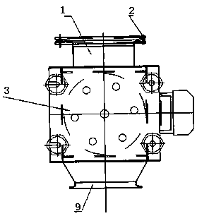
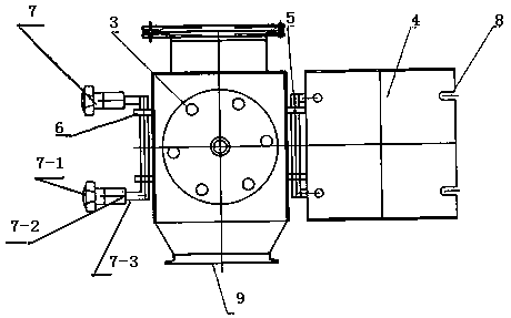
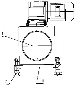
[0010] Specific examples figure 1 and figure 2 As shown, the middle part of the iron removal box 3 is a square, and gradually shrinks to the two ports along the middle part of the iron removal box. The shape of the discharge port and the feed port is circular. Further, the feed port and the discharge port are circular ports, and the circular port has a folded edge outwards and is connected to another interface through a quick-connect clamp. Any side of the square part in the middle of the iron box body is provided with an open...


PUM


Abstract

The invention discloses an iron remover with a magnetic bar capable of being mounted fast. The middle of an iron removing box is a box, and two end openings of the iron removal box serve as a feedingport and a discharging port correspondingly. An opening for allowing a box door to be mounted is formed in an arbitrarily side of the box in the middle of the iron removal box, and the box door capable of being opened is mounted on the opening. One side of the box door is hinged and fixed through a shaft, and U-shaped lock grooves corresponding to locking devices are machined in the box door on the opened side. The two U-shaped lock grooves are formed in the box door up and down, and the locking devices for locking the box door are welded to the upper shaft end and the lower shaft end of a rotary shaft. The two ends of the rotary shaft are assembled and mounted on the opened side face of the open opening of the iron removal box through nuts. According to the technical scheme, the sealing box door and the box can be opened or closed fast, iron powder can be removed conveniently, and the magnetic bar can be replaced conveniently; and the feeding port and the discharging port formed in the box can be fast connected with a vacuum feeding bin through fast connecting hoops. The iron remover is simple in structure, the box door can be opened conveniently, and therefore work efficiency isimproved.

Description

technical field [0001] The invention relates to an iron remover, which is suitable for the screening of dry powder, especially the screening of raw materials in the food and drug industry. Background technique [0002] With the development of society and the needs of people's lives, the industry has an increasing demand for various ultra-fine powder materials. Since the ultra-fine powder will be mixed with iron powder when it is ground, although it has been classified and screened, the iron powder mixed with the ultra-fine powder cannot be effectively removed, resulting in a decline in the quality of the ultra-fine powder. [0003] The patent number authorized by the State Patent Office is: 200820047450.6, name: "rotating magnetic rod type dry powder iron remover" including the box (1), bracket (7), inlet (2) and outlet (6), the box (1) Install (7), install the feed inlet (2) above the box (1), and install the outlet (6) below the box (1), which is characterized in that it ...

Claims


Application Information

Patent Timeline
Patent Type & Authority Applications(China)
IPC IPC(8): B03C1/02
CPCB03C1/02
Inventor 孟保亮秦英王兵卢恩同孟新峰
Owner XINXIANG ZHEN YING MACHINERY EQUIP CO LTD
Why Eureka
Try Eureka