Air knot type yarn knotting method

A yarn and air technology, which is applied in the field of air knot yarn knotting, can solve problems such as too large knots and too hard knots, and achieve the effect of meeting the needs of continuous production

Inactive Publication Date: 2018-07-31
JUSHI GRP CO
View PDF11 Cites 3 Cited by
  • Summary
  • Abstract
  • Description
  • Claims
  • Application Information

AI Technical Summary

Problems solved by technology

The knotting method disclosed in the above-mentioned comparative document has the disadvantages of excessively large and hard knots

Method used


Image

  • Air knot type yarn knotting method
  • Air knot type yarn knotting method
  • Air knot type yarn knotting method

Examples


Embodiment 1

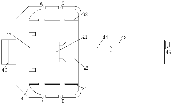
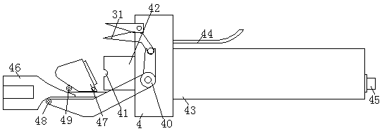
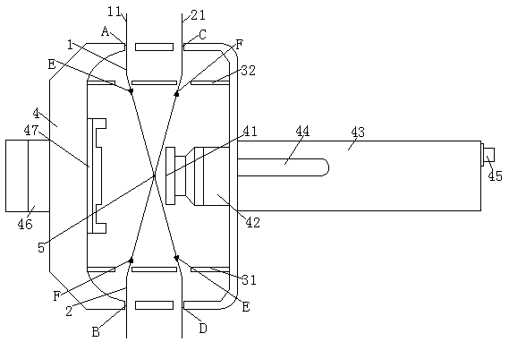
[0030] The air-knotted yarn knotting method in the present embodiment is used for knotting and connecting No. 1 yarn 1 and No. 2 yarn 2. One end of No. 1 yarn 1 is No. 1 yarn head end 11, and One end of No. yarn 2 is No. 2 yarn tail end 21, and No. 1 cutting blade 31 and No. 2 cutting blade are installed in the blowing knotter 4 for knotting No. 1 yarn 1 and No. 2 yarn 2 32. The air blowing knotter 4 is provided with a No. 1 bayonet A, a No. 2 bayonet B, a No. 3 bayonet C, and a No. 4 bayonet D. The air blowing knotter 4 includes a propulsion device 46, an air blowing device cover door 47, No. 1 propulsion pulley 48, No. 2 propulsion pulley 49 and driving force arm 40; Air blowing knotter 4 comprises propulsion device 46, air blowing device cover door 47, No. 1 propulsion pulley 48, No. 2 propulsion pulley 49 and push The force arm 40 is the same as the prior art, and the blowing device 42 is installed in the blowing knotter 4, and the blowing device 42 is positioned at the mi...

Embodiment 2

[0041] The air-knotted yarn knotting method in the present embodiment is used for knotting and connecting No. 1 yarn 1 and No. 2 yarn 2. One end of No. 1 yarn 1 is No. 1 yarn head end 11, and One end of No. yarn 2 is No. 2 yarn tail end 21, and No. 1 cutting blade 31 and No. 2 cutting blade are installed in the blowing knotter 4 for knotting No. 1 yarn 1 and No. 2 yarn 2 32. The air blowing knotter 4 is provided with a No. 1 bayonet A, a No. 2 bayonet B, a No. 3 bayonet C, and a No. 4 bayonet D. The air blowing knotter 4 includes a propulsion device 46, an air blowing device cover door 47, No. 1 propulsion pulley 48, No. 2 propulsion pulley 49 and driving force arm 40; Air blowing knotter 4 comprises propulsion device 46, air blowing device cover door 47, No. 1 propulsion pulley 48, No. 2 propulsion pulley 49 and push The force arm 40 is the same as the prior art, and the blowing device 42 is installed in the blowing knotter 4, and the blowing device 42 is positioned at the mi...


PUM


Abstract

The invention relates to an air knot type yarn knotting method for knotting a first yarn and a second yarn. The air knot type yarn knotting method comprises the following steps: one section of the first yarn is measured from the head end of the first yarn, and one section of the second yarn is measured from the tail end of the second yarn; an air blowing knotting machine is selected according to densities of the first yarn and the second yarn, and the air pressure of the air blowing knotting machine is adjusted; the first yarn penetrates through a first clamping port and a fourth clamping portin sequence, and the second yarn penetrates through the second clamping port and a third clamping port in sequence; or the first yarn penetrates through the second clamping port and the third clamping port in sequence, and the second yarn penetrates through the first clamping port and the fourth clamping port in sequence; the first yarn and the second yarn are knotted through the air blowing knotting machine after intersection; and the knotted section of the second yarn and the knotted section of the first yarn are blown to the knotting side through an air blowing outlet to form knotted yarns. The knotting method can be applied to enable the yarns to smoothly penetrate through yarn guide holes, and facilitates industrial application.

Description

technical field [0001] The invention relates to an air-knot yarn knotting method, which is suitable for the connection between yarns, especially for the connection between glass fiber plied untwisted roving yarn clusters. Background technique [0002] At present, the glass fiber plied rovings packaged in pallets are packaged independently and without connection between each yarn cluster. During use, after the previous yarn roll is used up, it needs to be shut down to connect the next yarn roll to continue production, which greatly affects the use efficiency of glass fiber yarn and cannot meet the needs of automated high-efficiency production. Connecting two yarn clusters end to end is suitable for continuous production. However, due to the characteristics of glass fiber yarns, knotting in ordinary ways will cause large knots. In the later production process, the yarn will pass through the guide. The yarn hole is not smooth, which affects the use efficiency. At the same tim...

Claims


Application Information

Patent Timeline
IPC IPC(8): B65B13/26
Inventor 费建春马明锋
Owner JUSHI GRP CO
Why Eureka
Try Eureka