A battery pole group coating machine
What is Al technical title?
Al technical title is built by PatSnap Al team. It summarizes the technical point description of the patent document.
A technology of coating machine and storage battery, which is applied in the field of storage battery machinery manufacturing and automatic coating, which can solve the problems of unguarantable battery quality, low degree of automation and low production efficiency, so as to improve accuracy and cutting efficiency and optimize production process , The effect of low manufacturing cost
Active Publication Date: 2017-06-16
ZHUZHOU YINGDING AUTOMATION EQUIP TECH
View PDF5 Cites 2 Cited by
Summary
Abstract
Description
Claims
Application Information
AI Technical Summary
This helps you quickly interpret patents by identifying the three key elements:
Problems solved by technology
Method used
Benefits of technology
Problems solved by technology
[0002] The existing lead-acid battery pole group laminations are stacked by a semi-automatic lamination mechanism to stack the positive and negative plates and separator paper, and then the artificial coating film is put into the pole group turnover box and flows to the next casting and welding process. The purpose of the coating is to In order to protect each electrode group from damage during the assembly process; at present, the coating is mainly performed manually. The existing coating method on the market is not highly automated, the quality of the battery cannot be guaranteed, the production efficiency is low, the cost is high, and the stability is poor. There are certain defects in the structure of each component
Method used
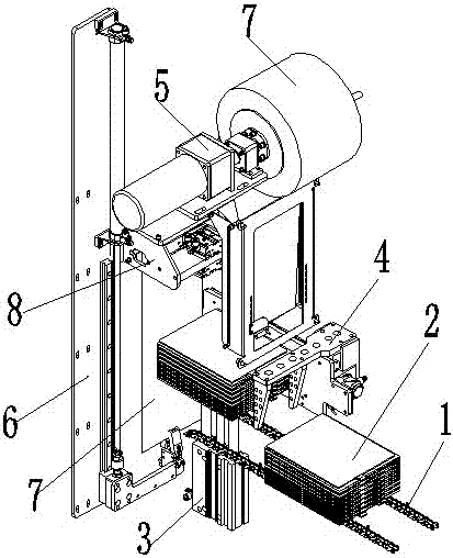
Image
Click on the blue label to locate the original text in one second.
Reading with bidirectional positioning of images and text.
Examples
Embodiment Construction
[0024] In order to enable those skilled in the art to better understand the technical solutions of the present invention, the present invention will be further described in detail below in conjunction with the accompanying drawings and specific embodiments.
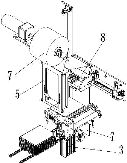
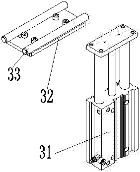
[0025] refer to figure 1 , figure 2 , Figure 8 and Figure 9 , a battery pole group coating machine of the present invention, comprising a chain 1, a pole group 2, a lifting mechanism 3, a pushing mechanism 4, a film feeding mechanism 5, a film pulling mechanism 6, a film 7, a film cutting mechanism 8, the chain 1 The pole group 2 is arranged on the top, the lifting mechanism 3 is arranged in the middle and lower part of the end of the chain 1, the pushing mechanism 4 is arranged above the side of the chain 1, and the film feeding mechanism 5 is arranged above the end of the chain 1 and the lifting mechanism 3, The film pulling mechanism 6 is arranged behind the chain 1 and the lifting mechanism 3, the film 7 is arra...
PUM
Abstract
The invention discloses a battery pole group coating machine, which comprises a chain, a pole group, a lifting mechanism, a pushing mechanism, a film feeding mechanism, a film pulling mechanism, a film, and a film cutting mechanism. There is a push mechanism, the film feeding mechanism is set above the end of the chain and the lifting mechanism, the film pulling mechanism is set behind the chain and the lifting mechanism, the film is set on the film feeding mechanism, and the film cutting mechanism is set on one side of the pulling mechanism ;The film pulling mechanism pulls the film of the film feeding mechanism into place and fixes the length, the film cutting mechanism cuts off the film, the chain conveys the pole group to the lifting mechanism, the lifting mechanism lifts the pole group, and the pushing mechanism lifts the pole group together with the film Push forward to the battery case or electrode group box or fixture, realize automatic electrode group coating and enter the battery case, electrode group box, and fixture at the same time, meet the needs of continuous automatic production, optimize the production process, and ensure the quality of the electrode group , the machine is reliable in operation, the coating effect is good, and the manufacturing cost is low.
Description
technical field [0001] The invention relates to the technical field of storage battery machinery manufacturing, in particular to the technical field of automatic coating used in storage battery production. Background technique [0002] The existing lead-acid battery pole group laminations are stacked by a semi-automatic lamination mechanism to stack the positive and negative plates and separator paper, and then the artificial coating film is put into the pole group turnover box and flows to the next casting and welding process. The purpose of the coating is to In order to protect each electrode group from damage during the assembly process; at present, the coating is mainly performed manually. The existing coating method on the market is not highly automated, the quality of the battery cannot be guaranteed, the production efficiency is low, the cost is high, and the stability is poor. There are certain defects in the structure of each part. Contents of the invention [00...
Claims
Application Information
Patent Timeline
Application Date:The date an application was filed.
Publication Date:The date a patent or application was officially published.
First Publication Date:The earliest publication date of a patent with the same application number.
Issue Date:Publication date of the patent grant document.
PCT Entry Date:The Entry date of PCT National Phase.
Estimated Expiry Date:The statutory expiry date of a patent right according to the Patent Law, and it is the longest term of protection that the patent right can achieve without the termination of the patent right due to other reasons(Term extension factor has been taken into account ).
Invalid Date:Actual expiry date is based on effective date or publication date of legal transaction data of invalid patent.